First Circuits

EXPERIMENTS

I worked with Amanda during this first session.

She brought an orange that wasn’t conductive enough to light up the LED. Same case for the CD I brought, because it is covered by plastic.

IMG_4895 IMG_4896


Then we tried to use metals (a metallic clip, and a piece of aluminum): IMG_4901


It worked!

IMG_5757IMG_4891

Finally, we used these conductive fabrics:

IMG_5758

And it worked too!

IMG_5759IMG_5760


We wanted to light up two LEDs on the same circuit. This is our process:IMG_4909

IMG_4910

The first one only is turned on. To light up the second one, we needed a second battery of 3Volts.

Here’s the result:

IMG_4902IMG_4905


We also used this black paint to connect the LED to the batterie and created a switch with the copper:

IMG_4915

IMG_4923IMG_4924

ePaper and Origami – Black Lighting Diamond – Eden

This is the process I’ve been through to create this Black Diamond ePaper.

First step: The realisation of the origami as a test to check if the idea I had in mind could work.

I’ve laser cut it to get perfect lines.

IMG_4994 IMG_4998

Second step: Do the same with the actual paper which is thicker and black.

I added these illustrations in order to let the light come out from the origami.

IMG_4999

This is the materials I used to create the circuit.

IMG_5003

Third step: Solder the circuit

IMG_5007 IMG_5009

Forth step: connect the generator to check if the circuit is correctly done

IMG_5013

This is the final result :

Daylight:

IMG_5033

Nightlight:

IMG_5029


FullSizeRender

Superman for a while_Eden Tartour

Superman for a while

I decided to hack the key space of the keyboard I had, and I connected it to this red blanket which made me think of Superman’s mantle. To make it work the way I wanted, I create a code that would play the soundtrack of Superman original film and will show a picture of him. When the circuit isn’t closed, the song stops playing and the image disappear.


This video show the process I went through, and there’s a few images too.

click here


IMG_5228


IMG_5229 IMG_5233 IMG_5254 IMG_5248

Triangle Soft Sensor

Material:

  • conductive fabric
  • resistive fabric
  • normal fabric (neoprene)
  • conductive thread
  • regular thread
  • foam

Steps:

  • Create two separate shapes of your choice (I decided to make a triangle), because we’ll work on two layers of conductive fabric and they shouldn’t touch each other.
  • Follow this order: regular fabric, conductive fabric, restive fabric and foam. Sew them with conductive thread twice.
  • IMG_5274
  • Sew the two layers together with regular thread.

IMG_5281

  • Your sensor is ready to be used!

IMG_5278

Textilo – Noisy Socks


We made a Textilo!


You can follow the essential steps to create a textilo:

First we laser cut this circuit on conductive fabric that we sticked to a regular fabric (the black one).IMG_5557

Then, we soldered the circuit with the different components: the generator, the speaker and the soft sensor that we made last session (I personally made a new one that you can see bellow).

IMG_5565 IMG_5573

Here’s my new sensor that’s more adapted to the socks I’m making because of its form.

IMG_5660 IMG_5661 IMG_5663 IMG_5664


With those crocodiles we’re able to check if our circuit is working.IMG_5665 IMG_5684

And it is working!!!!

(I decided to glue the textilo for security reasons, you’re not forced to)

Then I started sewing the whole circuit to my socket. I created two pockets: one to put the generator, and the other for the speaker. I decided to keep the textilo apparent for esthetic reasons (I like the colors and the shape of it). I could always cover it with fabric if I wanted to.

IMG_5855 IMG_5859

I’m now wearing this socket that make noise when you press on the floor.

IMG_5879 IMG_5880 IMG_5882 IMG_5887 IMG_5888


You can check out this compilation of insane videos that I took with this socket 😉


Flip Flop Constellations Generative Drawing

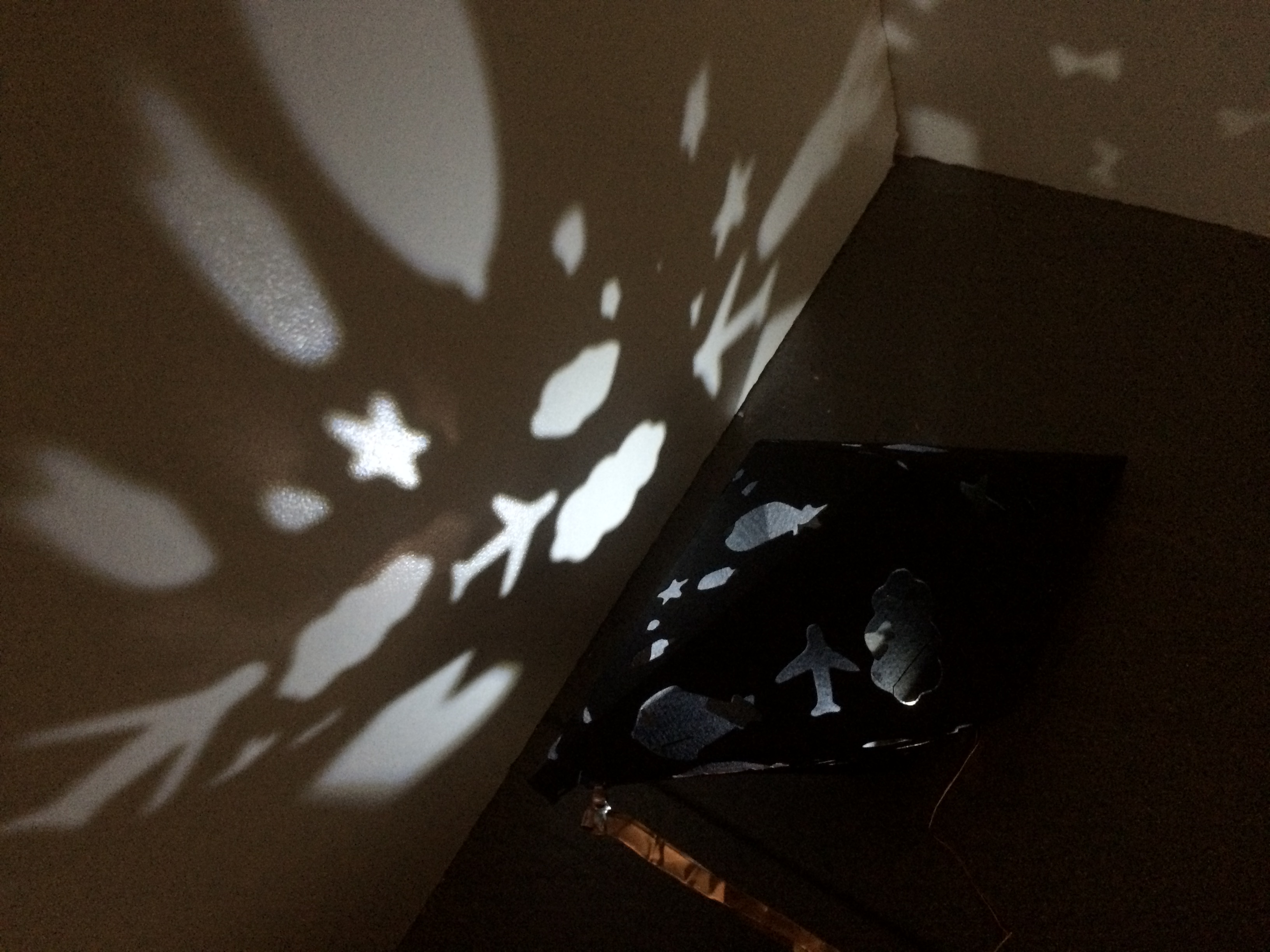
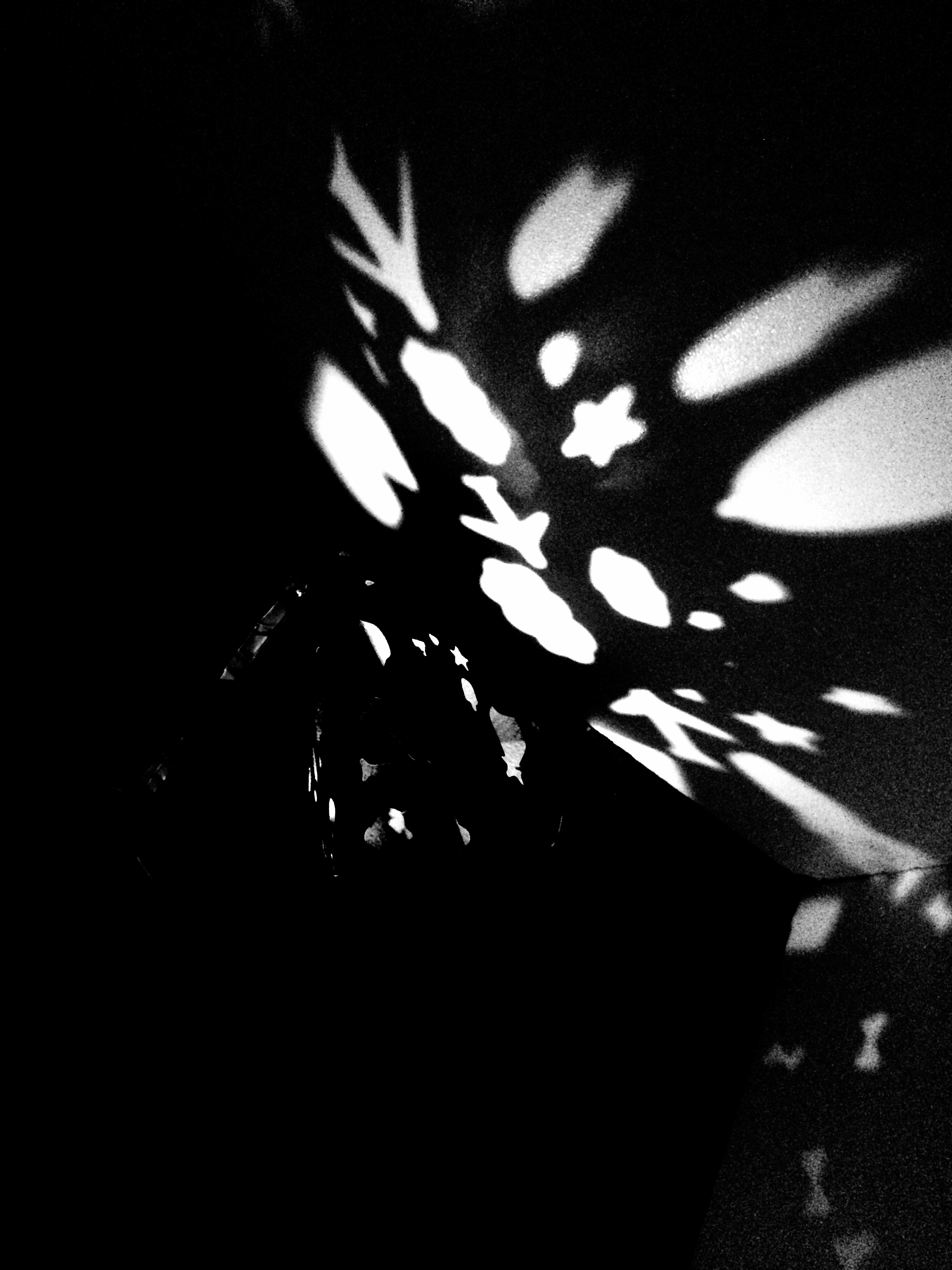
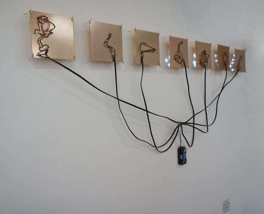
For this last exercise, I wanted to develop a project I made last Semester. It was about representing my family tree in a new way, using the zodiac sign’s constellation of each member of my family. I represented them all using in total 52 LEDs that represented the constellations of these zodiac signs : Leo, Aquarius, Pisces, Virgo, Sagittarius, Libra. 

Here’s a picture of the work I made earlier:

Screen-Shot-2015-05-17-at-4.20.00-PM-2k6zmdz

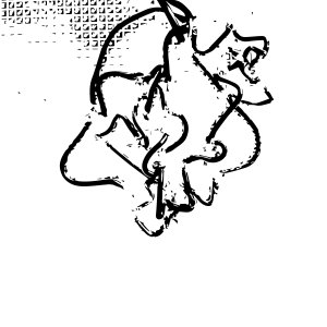
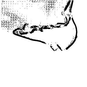
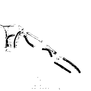
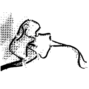
I took pictures of each constellations and created patterns on Illustrator:

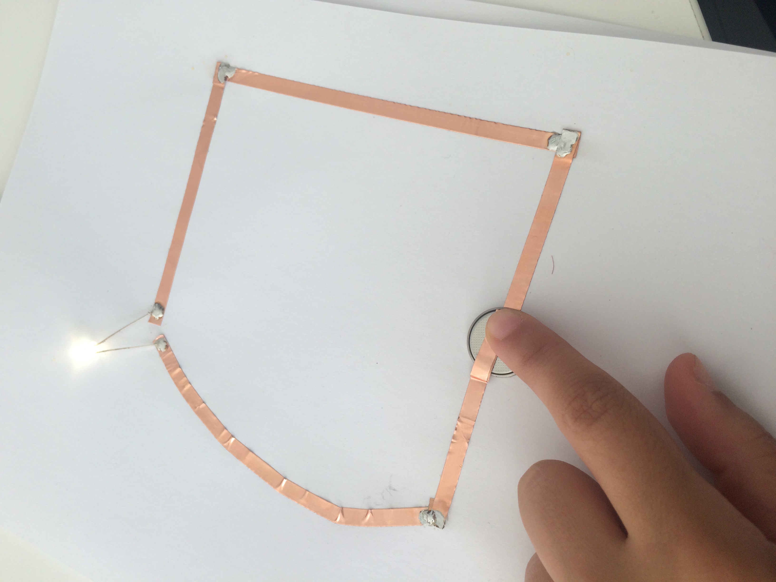
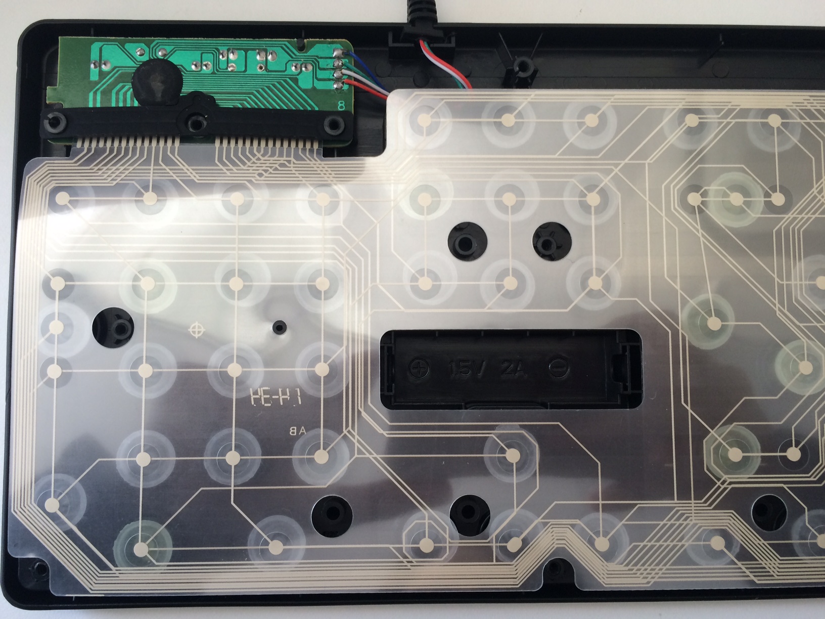
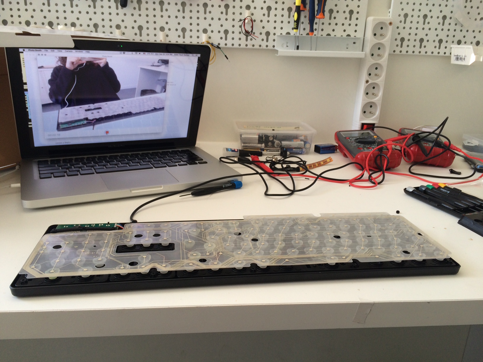
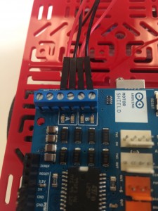
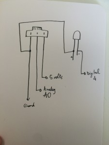
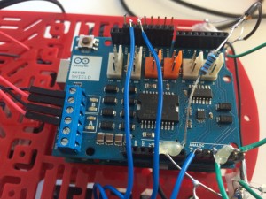
I re-used the 52 LEDs and connected them to a Lylipad. The goal was to be able to control the intensity of the lights. And depending on the intensity, one of the 7 drawings (see above) would appear on the Processing code I made. It generates colorful drawings at a certain speed.


This is the code I made for Processing:


import processing.serial.*;

import cc.arduino.*;
import org.firmata.*;

Arduino arduino;

int number= 0;

int analogInPin = 5;
int analogOutPin = 10;

int sensorValue = 0;
int outputValue = 0;

PImage[] imgs = new PImage[7];
void setup() {
size (800, 800);
stroke(255);
background(random(256));
smooth();

println(Arduino.list());

arduino = new Arduino(this, “/dev/tty.usbserial-AI02L4YN”, 57600);
arduino.pinMode(analogInPin, Arduino.OUTPUT);
arduino.pinMode(analogOutPin, Arduino.INPUT);

for ( int i = 0; i< imgs.length; i++ )
{
imgs[i] = loadImage( “mask-0” + i + “.png” );
}

//control the frame rate with the intensity of the lights
frameRate(50);
}

void draw() {

sensorValue = arduino.analogRead(analogInPin);
println(sensorValue);
// drawing rectangles
int randomX;
int randomY;
int randomH;
int randomW;

//random size of rect
randomH = int(random(130));
randomW = int(random(130));

//random rect start
randomX = int(random(800));
randomY = int(random(800));

//random color
int r = int(random(256));
int g = int(random(256));
int b = int(random(256));

stroke(r, g, b);
fill (r, g, b);
strokeWeight(2);
rect(randomX, randomY, randomW, randomH);
// if intensity between x and x then upload the image “belier”
if (sensorValue == 0 && sensorValue < 146) {
image (imgs[0], 0, 0, imgs[0].width/4, imgs[0].height/4);
} else if (sensorValue > 146 && sensorValue < 292) {
image (imgs[1], 0, 0, imgs[1].width/4, imgs[1].height/4);
} else if (sensorValue > 292 && sensorValue < 438 ) {
image (imgs[2], 0, 0, imgs[2].width/4, imgs[2].height/4);
} else if (sensorValue > 438 && sensorValue < 584 ) {
image (imgs[3], 0, 0, imgs[3].width/4, imgs[3].height/4);
} else if (sensorValue > 584 && sensorValue < 730 ) {
image (imgs[4], 0, 0, imgs[4].width/4, imgs[4].height/4);
} else if (sensorValue > 730 && sensorValue < 876 ) {
image (imgs[5], 0, 0, imgs[5].width/4, imgs[5].height/4);
} else if (sensorValue > 876 && sensorValue < 1023 ) {
image (imgs[6], 0, 0, imgs[6].width/4, imgs[6].height/4);
}
}
//creates rectangles at mouse point when clicked
void mousePressed() {
rect(int(random(150)), int(random(150)), mouseX, mouseY);
}

void keyPressed() {
if (key == ‘s’) {
println(“Saving…”);
String s = “led_astro_drawing” + nf(number, 4) + “.jpg”;
save(s);
number++;
println(“Done saving.”);
}
}


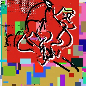
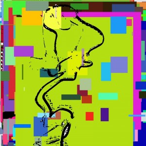
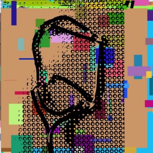
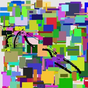
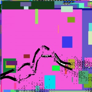
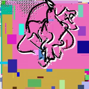
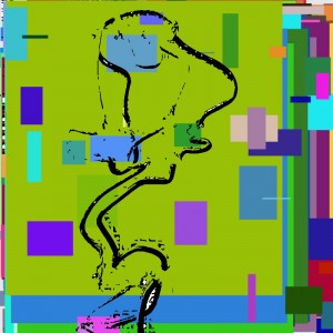
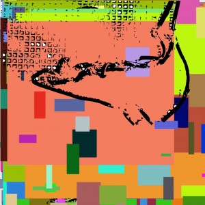
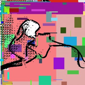
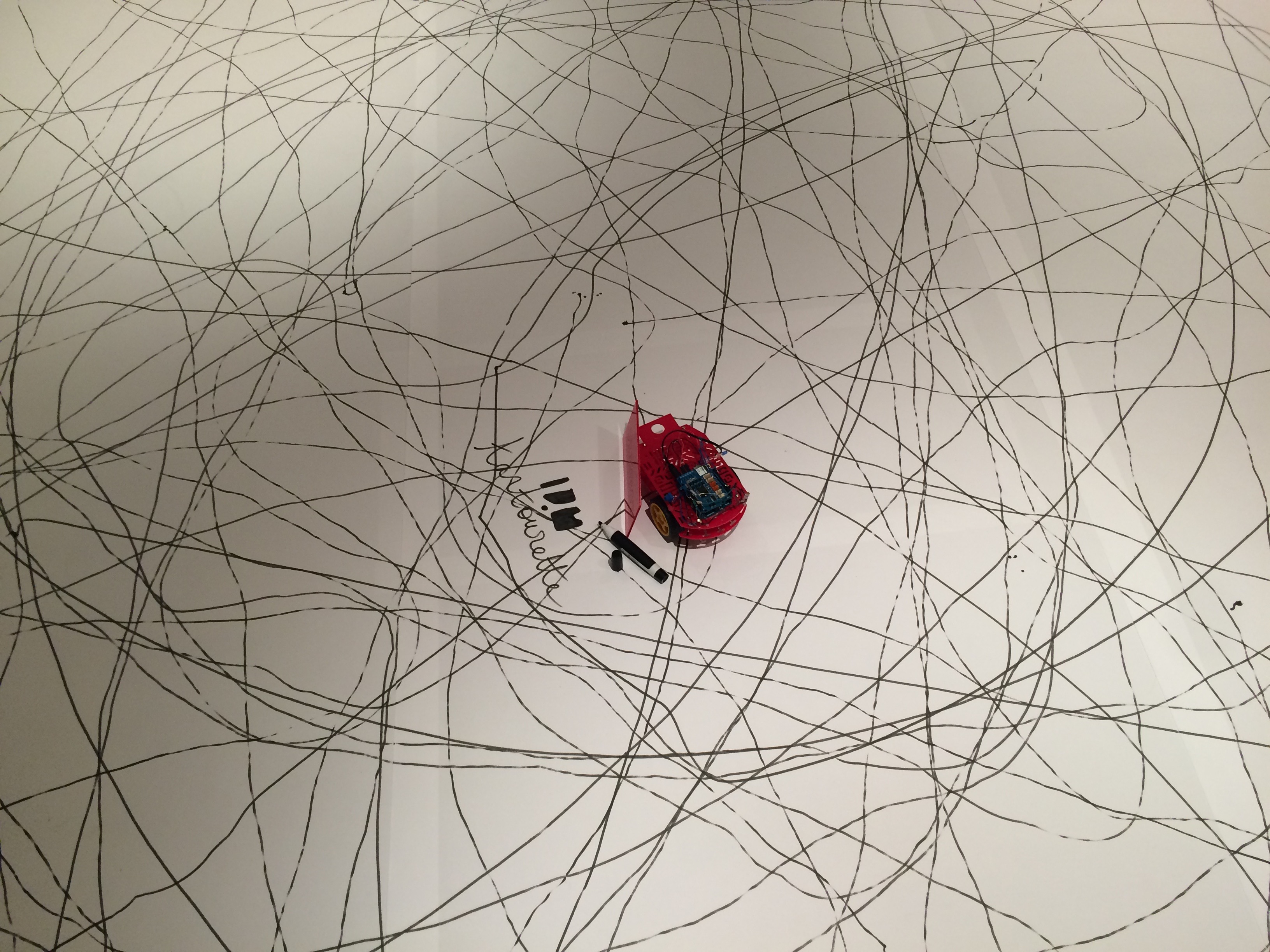
And this is the result I got:


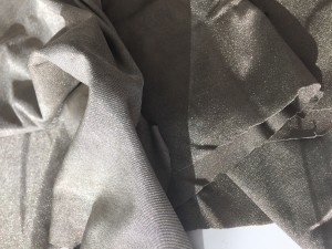
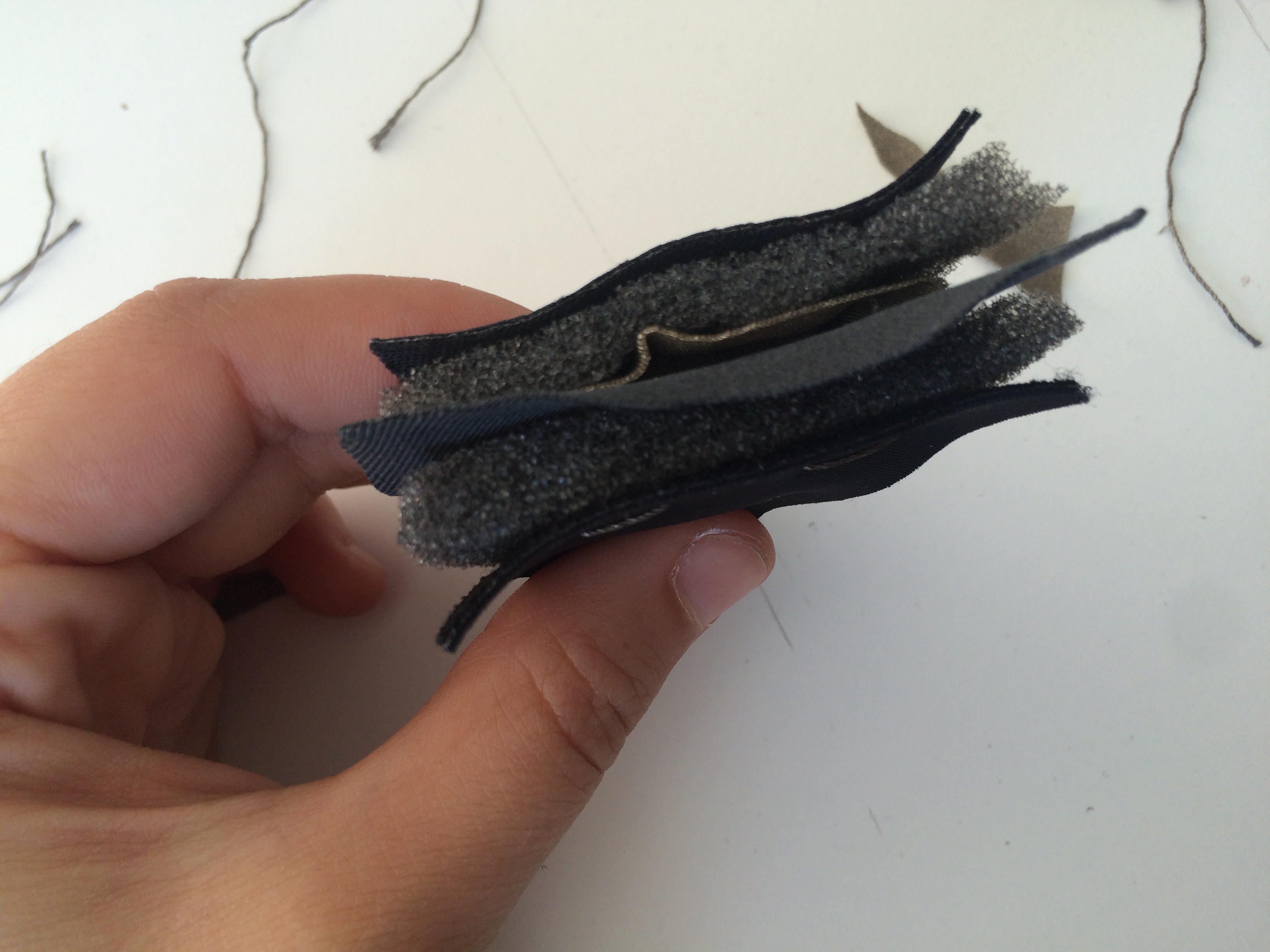
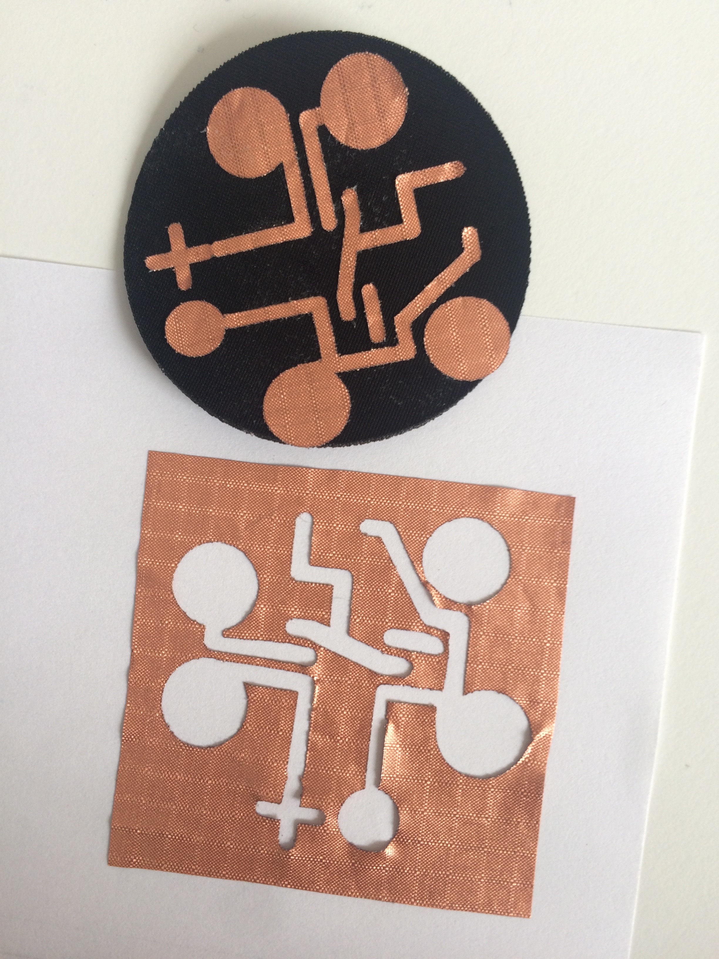
Finally, I decided to print them on fabrics following the idea that even though we can share the same Zodiac Sign we are all different and we all interpret it differently. That’s why the representation of each zodiac sign can never be the same.

Capture d’écran 2015-11-26 à 17.18.18

Light Following DrawBot

My inspirations:

The Czech writer Karel Capek used the term « robot » for the first time in the context of a play called « Rossum’s Universal Robots » (or « R.U.U ») in 1921. The play staged a man who created a robot that would kill him later on. The irony is fascinating, wit robotics we are creating our best ennemis. In order to prevent such a situation, twenty years later (in 1942), the science fiction writer Isaac Asimov wrote in his short story « Runaround »  the « Three Laws of Robotics » which are:

1 A robot may not injure a human being or, through inaction, allow a human being to come to harm.

2 A robot must obey the orders given it by human beings, except where such orders would conflict with the First Law.

3 A robot must protect its own existence as long as such protection does not conflict with the First or Second Laws.

In later books, Asimov added a zeroth law:

0 A robot may not harm humanity, or, by inaction, allow humanity to come to harm.

These rules avoid a situation where robots could take the control of our humanity and become stronger and more powerful than us.

For this project, I tried to consider both digital and physical worlds to create my Light Following Drawbot. I wanted to establish a connection and interaction between the created robot and us, as humans. With this project I want the robot and the human to be reconciled and I want them to collaborate in the artistic world to bring some novelty in the tracing of a drawing.

My final project:

I decided to create my own drawing robot that users could control using the flashlight of their smartphones. This interactive robot would follow the light and draw on his way.

PLEASE HAVE A LOOK AT THE FINAL VIDEO HERE

Instructable:

You can find out how I made it through this intructables page I created here

Or you can read the steps bellow:

To make it, here’s the list of materials you need:

This is a drawing of all the connections you need to make for the drawbot.

Sketch 2_bb

  1. Assemble the Robot Chassis. Use the instructions to assemble all the parts correctly. Take your time and try to avoid mistakes. You have to be patient for this project.
  2. Connect the motors to the Motor Shield, and then to the Arduino. Connect the positive side (red) of the first motor the + on the “A” section of the motor shield. The negative side (black) of this same motor to the – on the “A” section. Repeat this with the second motor on the “B” section. Then, place the motor shield on top of the Arduino. It will connect.
  3. Test the motors with a simple code to check if it works.                                                       
    1. void setup() {
      //Setup Channel A – right
      pinMode(12, OUTPUT); //Initiates Motor Channel A pin
      pinMode(9, OUTPUT); //Initiates Brake Channel A pin//Setup Channel B – left
      pinMode(13, OUTPUT); //Initiates Motor Channel B pin
      pinMode(8, OUTPUT); //Initiates Brake Channel B pin
      }void loop() {
      // go straight
      digitalWrite(12, LOW);
      digitalWrite(9, LOW);
      analogWrite(3, 200);digitalWrite(13, LOW);
      digitalWrite(8, LOW);
      analogWrite(11, 200);delay(1000);// go right
      digitalWrite(12, LOW);
      digitalWrite(9, LOW);
      analogWrite(3, 200);digitalWrite(13, LOW);
      digitalWrite(8, LOW);
      analogWrite(11, 20);
      delay(1000);// go left
      digitalWrite(12, LOW);
      digitalWrite(9, LOW);
      analogWrite(3, 20);digitalWrite(13, LOW);
      digitalWrite(8, LOW);
      analogWrite(11, 200);
      delay(1000);                                                                                                                                                               }                                                                                                                                                                                     Vidéo du 03-12-2015 à 11.28
  4. Now, connect the LDRs (with the resistors) to the Arduino. (check the image bellow) You have to connect the first LDR (that we call LDR0) to a 10k resistor. One pin goes to 5V, the other that is connected to the 10k resistor goes to an Analog pin (we choose the A2 pin) and the last one that comes from the resistor goes to the ground. Repeat this action with the second LDR (that we call LDR1) which goes to the 5V too, the pin A3, and the ground.
  5. Test the LDRs with a simple code to check if they work                                                           int LDR0 = A2; // right
    int LDR1 = A3; // leftvoid setup() {//ldr
    pinMode(LDR0, INPUT);
    pinMode(LDR1, INPUT);
    Serial.begin(9600);
    }void loop() {int valueLDR0 = analogRead(LDR0);
    int valueLDR1 = analogRead(LDR1)Serial.print(valueLDR0);
    Serial.print(“\t”);
    Serial.print(valueLDR1);
    Serial.print(“\t”);}

    • Then, make some tests by hiding one LDR and the other and check the values with the serial monitor
  6. Make a code that connects the motors to the LDRs                                                                   int LDR0 = A2; // right
    int LDR1 = A3; // left
    int threshold = 400; // you can change this value depending on the light of your environmentvoid setup() {//ldr
    pinMode(LDR0, INPUT);
    pinMode(LDR1, INPUT);
    Serial.begin(9600);//Setup Channel A – right
    pinMode(12, OUTPUT); //Initiates Motor Channel A pin
    pinMode(9, OUTPUT); //Initiates Brake Channel A pin//Setup Channel B – left
    pinMode(13, OUTPUT); //Initiates Motor Channel B pin
    pinMode(8, OUTPUT); //Initiates Brake Channel B pin
    }void loop() {int valueLDR0 = analogRead(LDR0);
    int valueLDR1 = analogRead(LDR1)if (threshold > valueLDR0 + 50 && threshold > valueLDR1 + 50) {digitalWrite(12, LOW);
    digitalWrite(9, LOW);
    analogWrite(3, 200);digitalWrite(13, LOW);
    digitalWrite(8, LOW);
    analogWrite(11, 200);delay(300);if (valueLDR0 > threshold || valueLDR1 > threshold) {
    if (valueLDR0 > valueLDR1) {
    //right
    digitalWrite(12, LOW);
    digitalWrite(9, LOW);
    analogWrite(3, 200);
    //left
    digitalWrite(13, LOW);
    digitalWrite(8, LOW);
    analogWrite(11, 20);delay(200);
    analogWrite(11, 200);
    delay(500);
    }else if (valueLDR1 > valueLDR0) {
    //right
    digitalWrite(12, LOW);
    digitalWrite(9, LOW);
    analogWrite(3, 20);
    //left
    digitalWrite(13, LOW);
    digitalWrite(8, LOW);
    analogWrite(11, 200);delay(200);
    analogWrite(3, 200);
    delay(500);}
    }
    } else {
    digitalWrite(9, HIGH); // stop right motor
    digitalWrite(8, HIGH); // stop left motor
    }

    Serial.print(valueLDR0);
    Serial.print(“\t”);
    Serial.print(valueLDR1);
    Serial.print(“\t”);

    }   wordpress

  7. Connect a potentiometer and an LED to the circuit, on the Arduino. (check the image bellow). The negative side of the LED goes to the digital pin 4. Its positive side goes to the first pin of the potentiometer which goes to the Ground. The second pin of the potentiometer goes the Analog pin A0, and the last pin goes to the 5V.
  8. Test the new connections with final the code
    int LDR0 = A2; // right
    int LDR1 = A3; // left
    int threshold;
    int led1 = 4;
    int potent = A0;void setup() {// led and potentiometer
    pinMode (led1, OUTPUT);
    pinMode(potent, INPUT);//Setup Channel A – right
    pinMode(12, OUTPUT); //Initiates Motor Channel A pin
    pinMode(9, OUTPUT); //Initiates Brake Channel A pin//Setup Channel B – left
    pinMode(13, OUTPUT); //Initiates Motor Channel B pin
    pinMode(8, OUTPUT); //Initiates Brake Channel B pin//ldr
    pinMode(LDR0, INPUT);
    pinMode(LDR1, INPUT);
    Serial.begin(9600);
    }void loop() {threshold = analogRead(potent);
    int valueLDR0 = analogRead(LDR0);
    int valueLDR1 = analogRead(LDR1) + 200;if (threshold > valueLDR0 + 50 && threshold > valueLDR1 + 50) {
    digitalWrite(4, HIGH); // turn on leddigitalWrite(12, LOW);
    digitalWrite(9, LOW);
    analogWrite(3, 200);digitalWrite(13, LOW);
    digitalWrite(8, LOW);
    analogWrite(11, 200);delay(300);if (valueLDR0 > threshold || valueLDR1 > threshold) {
    if (valueLDR0 > valueLDR1) {
    //right
    digitalWrite(12, LOW);
    digitalWrite(9, LOW);
    analogWrite(3, 200);
    //left
    digitalWrite(13, LOW);
    digitalWrite(8, LOW);
    analogWrite(11, 20);delay(200);
    analogWrite(11, 200);
    delay(500);
    }else if (valueLDR1 > valueLDR0) {
    //right
    digitalWrite(12, LOW);
    digitalWrite(9, LOW);
    analogWrite(3, 20);
    //left
    digitalWrite(13, LOW);
    digitalWrite(8, LOW);
    analogWrite(11, 200);delay(200);
    analogWrite(3, 200);
    delay(500);

    }
    }
    } else {
    digitalWrite(9, HIGH); // stop right motor
    digitalWrite(8, HIGH); // stop left motor
    digitalWrite(4, LOW); // turn off led
    }
    //read values
    Serial.print(valueLDR0);
    Serial.print(“\t”);
    Serial.print(valueLDR1);
    Serial.print(“\t”);
    Serial.println(threshold);
    }

  9. Use hard glue to keep the connections together. Be careful to keep your connections, they might not connect anymore if the hard glue disconnect the wires.
  10. Attach a pen to the robot !!
  11. Make the robot looks good, the way you want. I decided to use the same red plexiglass as the chassis to keep a cohesion. I lasercut it, and engraved the name of this project “Drawbot” and my name (tartourette). I also cut small rectangle to fix the top at a certain height (8cm in my case). Using hard glue I fixed them in a balanced way.

ENJOY YOUR LIGHT FOLLOWING DRAWING ROBOT !!!!!! AND MAKE GREAT ART

You can have a look at some pictures of the drawbot:

IMG_7024IMG_7015IMG_6958 IMG_6961

This is the first drawing I made with a black sharpie:

IMG_6880 IMG_6887