Final Project


Overview

The theme of the final project is In Process. Over this course, we have discussed and examined processes of different practices and how to apply them to new tools, materials, ideas. We have also discussed how these tools, materials, and ideas influence process, especially in spaces where two processes collide (i.e. sewing and electronics, papercraft and interactive design). For your final project, you may choose whatever concept you like. As you move through this project, you should all consider your process deeply. Be critical of how you are approaching your concept, research, prototyping, and execution. Some questions to consider include: how do materials communicate to ideas? Do materials determine practice? What tools do you use and why? What tools do you want? What theoretical frameworks are you pulling from? How does the audience you are designing for impact your process?

Reprise

You may choose your concept for the final project. It must address ideas, processes, tools, and/or materials we have surveyed over the course. You will be graded on your implementation of the materials and processes we have been studying throughout the semester. You may work alone or collaboratively (team of 2 max). Below are the deliverables and calendar for the last three (!) classes.

Deliverables

  • Working prototype
  • In-class 8-10 minute presentation
  • Video and image documentation
  • Blog post containing all relevant links and reflection on your process
  • Instructable documenting how you made it
  • At least 1 feedback sessions to a Computional craft student in Parsons New York (these can be written via email or class blog or done through skype) – this will be due prior to the final and I will help you link to a student/project there. (See schedule below)

Final calendar

  • Nov 19 – Concept Proposal (working title, short paragraph, 1-2 precedents, at least one rough sketch)
  • Nov 26 – Updated Concept + Prototype
  • Dec 3 – Prototypes for in class feedback
  • Dec 10 – Prototypes + feedback to Computional craft
  • Dec 17 – Final + celebration!

Big Picture

As I mentioned, this is in collaboration with the Computional craft course (go to “Workshops” category to see work) at Parsons New-York. It will culminated in an exhibition and workshop/speaker series this spring. This is also part of a larger project called Crafting Tech that hopes to serve as an open platform for eCraft teachers and learners around the world to use in their classrooms and learning spaces.

Hybrid-Process-Overview-03

Light Following DrawBot

My inspirations:

The Czech writer Karel Capek used the term « robot » for the first time in the context of a play called « Rossum’s Universal Robots » (or « R.U.U ») in 1921. The play staged a man who created a robot that would kill him later on. The irony is fascinating, wit robotics we are creating our best ennemis. In order to prevent such a situation, twenty years later (in 1942), the science fiction writer Isaac Asimov wrote in his short story « Runaround »  the « Three Laws of Robotics » which are:

1 A robot may not injure a human being or, through inaction, allow a human being to come to harm.

2 A robot must obey the orders given it by human beings, except where such orders would conflict with the First Law.

3 A robot must protect its own existence as long as such protection does not conflict with the First or Second Laws.

In later books, Asimov added a zeroth law:

0 A robot may not harm humanity, or, by inaction, allow humanity to come to harm.

These rules avoid a situation where robots could take the control of our humanity and become stronger and more powerful than us.

For this project, I tried to consider both digital and physical worlds to create my Light Following Drawbot. I wanted to establish a connection and interaction between the created robot and us, as humans. With this project I want the robot and the human to be reconciled and I want them to collaborate in the artistic world to bring some novelty in the tracing of a drawing.

My final project:

I decided to create my own drawing robot that users could control using the flashlight of their smartphones. This interactive robot would follow the light and draw on his way.

PLEASE HAVE A LOOK AT THE FINAL VIDEO HERE

Instructable:

You can find out how I made it through this intructables page I created here

Or you can read the steps bellow:

To make it, here’s the list of materials you need:

This is a drawing of all the connections you need to make for the drawbot.

Sketch 2_bb

  1. Assemble the Robot Chassis. Use the instructions to assemble all the parts correctly. Take your time and try to avoid mistakes. You have to be patient for this project.
  2. Connect the motors to the Motor Shield, and then to the Arduino. Connect the positive side (red) of the first motor the + on the “A” section of the motor shield. The negative side (black) of this same motor to the – on the “A” section. Repeat this with the second motor on the “B” section. Then, place the motor shield on top of the Arduino. It will connect.
  3. Test the motors with a simple code to check if it works.                                                       
    1. void setup() {
      //Setup Channel A – right
      pinMode(12, OUTPUT); //Initiates Motor Channel A pin
      pinMode(9, OUTPUT); //Initiates Brake Channel A pin//Setup Channel B – left
      pinMode(13, OUTPUT); //Initiates Motor Channel B pin
      pinMode(8, OUTPUT); //Initiates Brake Channel B pin
      }void loop() {
      // go straight
      digitalWrite(12, LOW);
      digitalWrite(9, LOW);
      analogWrite(3, 200);digitalWrite(13, LOW);
      digitalWrite(8, LOW);
      analogWrite(11, 200);delay(1000);// go right
      digitalWrite(12, LOW);
      digitalWrite(9, LOW);
      analogWrite(3, 200);digitalWrite(13, LOW);
      digitalWrite(8, LOW);
      analogWrite(11, 20);
      delay(1000);// go left
      digitalWrite(12, LOW);
      digitalWrite(9, LOW);
      analogWrite(3, 20);digitalWrite(13, LOW);
      digitalWrite(8, LOW);
      analogWrite(11, 200);
      delay(1000);                                                                                                                                                               }                                                                                                                                                                                     Vidéo du 03-12-2015 à 11.28
  4. Now, connect the LDRs (with the resistors) to the Arduino. (check the image bellow) You have to connect the first LDR (that we call LDR0) to a 10k resistor. One pin goes to 5V, the other that is connected to the 10k resistor goes to an Analog pin (we choose the A2 pin) and the last one that comes from the resistor goes to the ground. Repeat this action with the second LDR (that we call LDR1) which goes to the 5V too, the pin A3, and the ground.
  5. Test the LDRs with a simple code to check if they work                                                           int LDR0 = A2; // right
    int LDR1 = A3; // leftvoid setup() {//ldr
    pinMode(LDR0, INPUT);
    pinMode(LDR1, INPUT);
    Serial.begin(9600);
    }void loop() {int valueLDR0 = analogRead(LDR0);
    int valueLDR1 = analogRead(LDR1)Serial.print(valueLDR0);
    Serial.print(“\t”);
    Serial.print(valueLDR1);
    Serial.print(“\t”);}

    • Then, make some tests by hiding one LDR and the other and check the values with the serial monitor
  6. Make a code that connects the motors to the LDRs                                                                   int LDR0 = A2; // right
    int LDR1 = A3; // left
    int threshold = 400; // you can change this value depending on the light of your environmentvoid setup() {//ldr
    pinMode(LDR0, INPUT);
    pinMode(LDR1, INPUT);
    Serial.begin(9600);//Setup Channel A – right
    pinMode(12, OUTPUT); //Initiates Motor Channel A pin
    pinMode(9, OUTPUT); //Initiates Brake Channel A pin//Setup Channel B – left
    pinMode(13, OUTPUT); //Initiates Motor Channel B pin
    pinMode(8, OUTPUT); //Initiates Brake Channel B pin
    }void loop() {int valueLDR0 = analogRead(LDR0);
    int valueLDR1 = analogRead(LDR1)if (threshold > valueLDR0 + 50 && threshold > valueLDR1 + 50) {digitalWrite(12, LOW);
    digitalWrite(9, LOW);
    analogWrite(3, 200);digitalWrite(13, LOW);
    digitalWrite(8, LOW);
    analogWrite(11, 200);delay(300);if (valueLDR0 > threshold || valueLDR1 > threshold) {
    if (valueLDR0 > valueLDR1) {
    //right
    digitalWrite(12, LOW);
    digitalWrite(9, LOW);
    analogWrite(3, 200);
    //left
    digitalWrite(13, LOW);
    digitalWrite(8, LOW);
    analogWrite(11, 20);delay(200);
    analogWrite(11, 200);
    delay(500);
    }else if (valueLDR1 > valueLDR0) {
    //right
    digitalWrite(12, LOW);
    digitalWrite(9, LOW);
    analogWrite(3, 20);
    //left
    digitalWrite(13, LOW);
    digitalWrite(8, LOW);
    analogWrite(11, 200);delay(200);
    analogWrite(3, 200);
    delay(500);}
    }
    } else {
    digitalWrite(9, HIGH); // stop right motor
    digitalWrite(8, HIGH); // stop left motor
    }

    Serial.print(valueLDR0);
    Serial.print(“\t”);
    Serial.print(valueLDR1);
    Serial.print(“\t”);

    }   wordpress

  7. Connect a potentiometer and an LED to the circuit, on the Arduino. (check the image bellow). The negative side of the LED goes to the digital pin 4. Its positive side goes to the first pin of the potentiometer which goes to the Ground. The second pin of the potentiometer goes the Analog pin A0, and the last pin goes to the 5V.
  8. Test the new connections with final the code
    int LDR0 = A2; // right
    int LDR1 = A3; // left
    int threshold;
    int led1 = 4;
    int potent = A0;void setup() {// led and potentiometer
    pinMode (led1, OUTPUT);
    pinMode(potent, INPUT);//Setup Channel A – right
    pinMode(12, OUTPUT); //Initiates Motor Channel A pin
    pinMode(9, OUTPUT); //Initiates Brake Channel A pin//Setup Channel B – left
    pinMode(13, OUTPUT); //Initiates Motor Channel B pin
    pinMode(8, OUTPUT); //Initiates Brake Channel B pin//ldr
    pinMode(LDR0, INPUT);
    pinMode(LDR1, INPUT);
    Serial.begin(9600);
    }void loop() {threshold = analogRead(potent);
    int valueLDR0 = analogRead(LDR0);
    int valueLDR1 = analogRead(LDR1) + 200;if (threshold > valueLDR0 + 50 && threshold > valueLDR1 + 50) {
    digitalWrite(4, HIGH); // turn on leddigitalWrite(12, LOW);
    digitalWrite(9, LOW);
    analogWrite(3, 200);digitalWrite(13, LOW);
    digitalWrite(8, LOW);
    analogWrite(11, 200);delay(300);if (valueLDR0 > threshold || valueLDR1 > threshold) {
    if (valueLDR0 > valueLDR1) {
    //right
    digitalWrite(12, LOW);
    digitalWrite(9, LOW);
    analogWrite(3, 200);
    //left
    digitalWrite(13, LOW);
    digitalWrite(8, LOW);
    analogWrite(11, 20);delay(200);
    analogWrite(11, 200);
    delay(500);
    }else if (valueLDR1 > valueLDR0) {
    //right
    digitalWrite(12, LOW);
    digitalWrite(9, LOW);
    analogWrite(3, 20);
    //left
    digitalWrite(13, LOW);
    digitalWrite(8, LOW);
    analogWrite(11, 200);delay(200);
    analogWrite(3, 200);
    delay(500);

    }
    }
    } else {
    digitalWrite(9, HIGH); // stop right motor
    digitalWrite(8, HIGH); // stop left motor
    digitalWrite(4, LOW); // turn off led
    }
    //read values
    Serial.print(valueLDR0);
    Serial.print(“\t”);
    Serial.print(valueLDR1);
    Serial.print(“\t”);
    Serial.println(threshold);
    }

  9. Use hard glue to keep the connections together. Be careful to keep your connections, they might not connect anymore if the hard glue disconnect the wires.
  10. Attach a pen to the robot !!
  11. Make the robot looks good, the way you want. I decided to use the same red plexiglass as the chassis to keep a cohesion. I lasercut it, and engraved the name of this project “Drawbot” and my name (tartourette). I also cut small rectangle to fix the top at a certain height (8cm in my case). Using hard glue I fixed them in a balanced way.

ENJOY YOUR LIGHT FOLLOWING DRAWING ROBOT !!!!!! AND MAKE GREAT ART

You can have a look at some pictures of the drawbot:

IMG_7024IMG_7015IMG_6958 IMG_6961

This is the first drawing I made with a black sharpie:

IMG_6880 IMG_6887


FINAL PROJECT: LED Light show + Projection Mapping

Final Project Proposal:

Led light show + Projection (Mapping)

I want to make an installation that is not too interactive and is more of a visual experience.

Materials:

  1. – 12 wood panels (6 = 35×35 cm, 6 = 26×26 cm)

    – 2 LED Strips (60 LEDS each)

    – Paper (Poster) Panels

    – Arduino Uno + USB cable (Type A to B)

    – Wires

    – 400 ohm resistor

    – Super Glue

    – Tape

    – Scissors

    – Wire cutters

    – Soldering Iron + Soldering Wire

    – Copper tape

    – 5 (9V) batteries or a battery with ~45 V

    – Projector (Optional: Tripod)

    – Optional: Speakers

    – Laptop

    Software:

    1. Processing 3 & 2 (Syphon doesn’t work with Processing 3)

    2. Arduino

    3. Movie Editing Software (iMovie, Final Cut Pro, Sony Vegas, etc)

    4. Projection Mapping Software (HeavyM, VPT7, MadMapper, TouchDesigner)


  2. IMG_3664IMG_3663
    IMG_3665

    Installation Plan

    LED Strip connection to the arduino

Make your own box

box-20151203_064912_3086673049

box-20151203_063118_598724

LED movement plan

Where to get code for the LED lights:

https://learn.adafruit.com/adafruit-neopixel-uberguide/overview


Generative Poetry


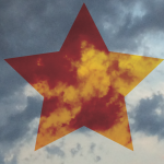
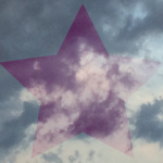
This project is based on the idea of creating the ability to write poetry about places all around the world–places you’ve been to or have never been to, places your friends have been to, or places you would like to go to. Although we may not be able to actually visit all of these places, now with the internet giving us the ability to see anywhere we would like in the world in under a second, we could be able to write poetry the same way. I created this project to help us connect visually and linguistically with anywhere you would like.


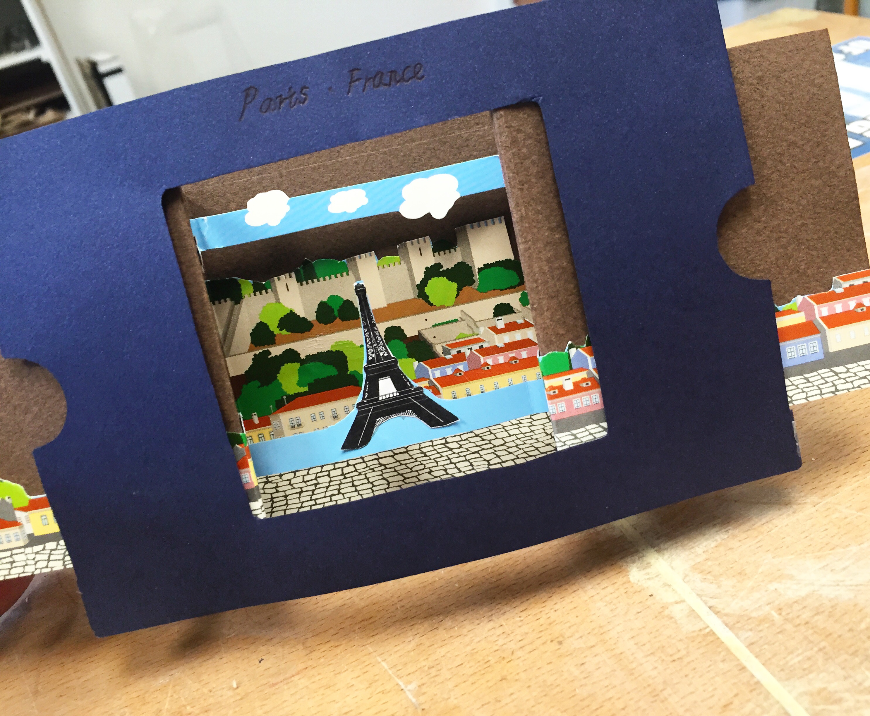
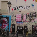
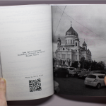
I started by asking friends to give me photos of places they’ve been, they grew up in, etc, and added a few of my own. The two images I’m showing are just examples–one is from Crimea and the other is from Paris. I’m lucky to have friends who come from all around the world to give me cool photos, but it doesn’t matter where they come from, some of my favorites are from home.

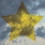
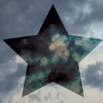
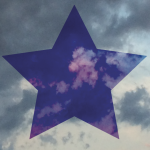
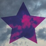
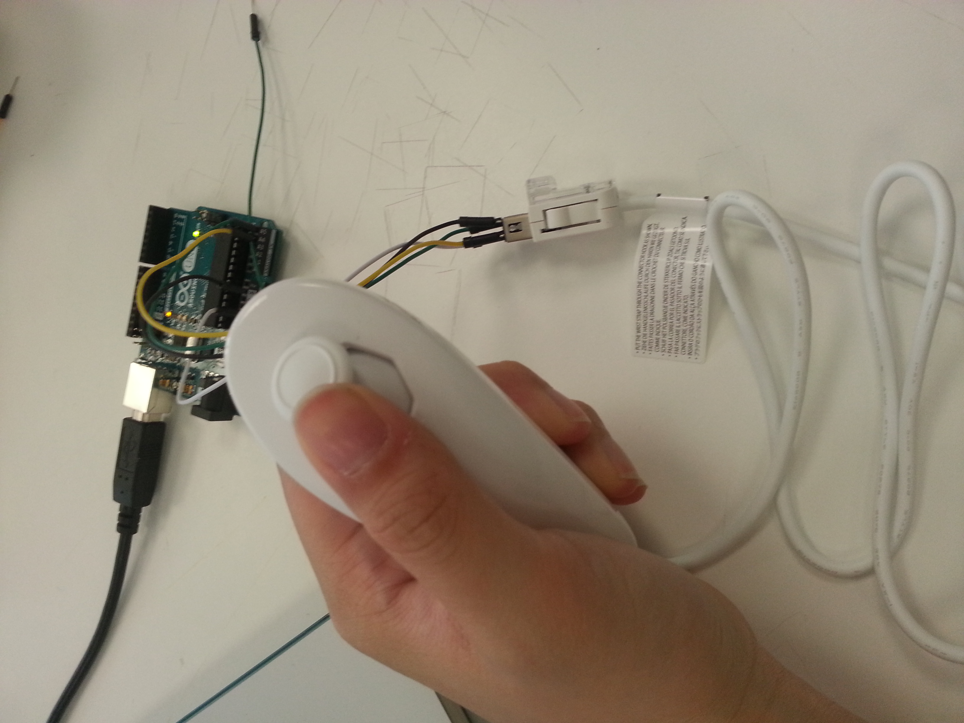
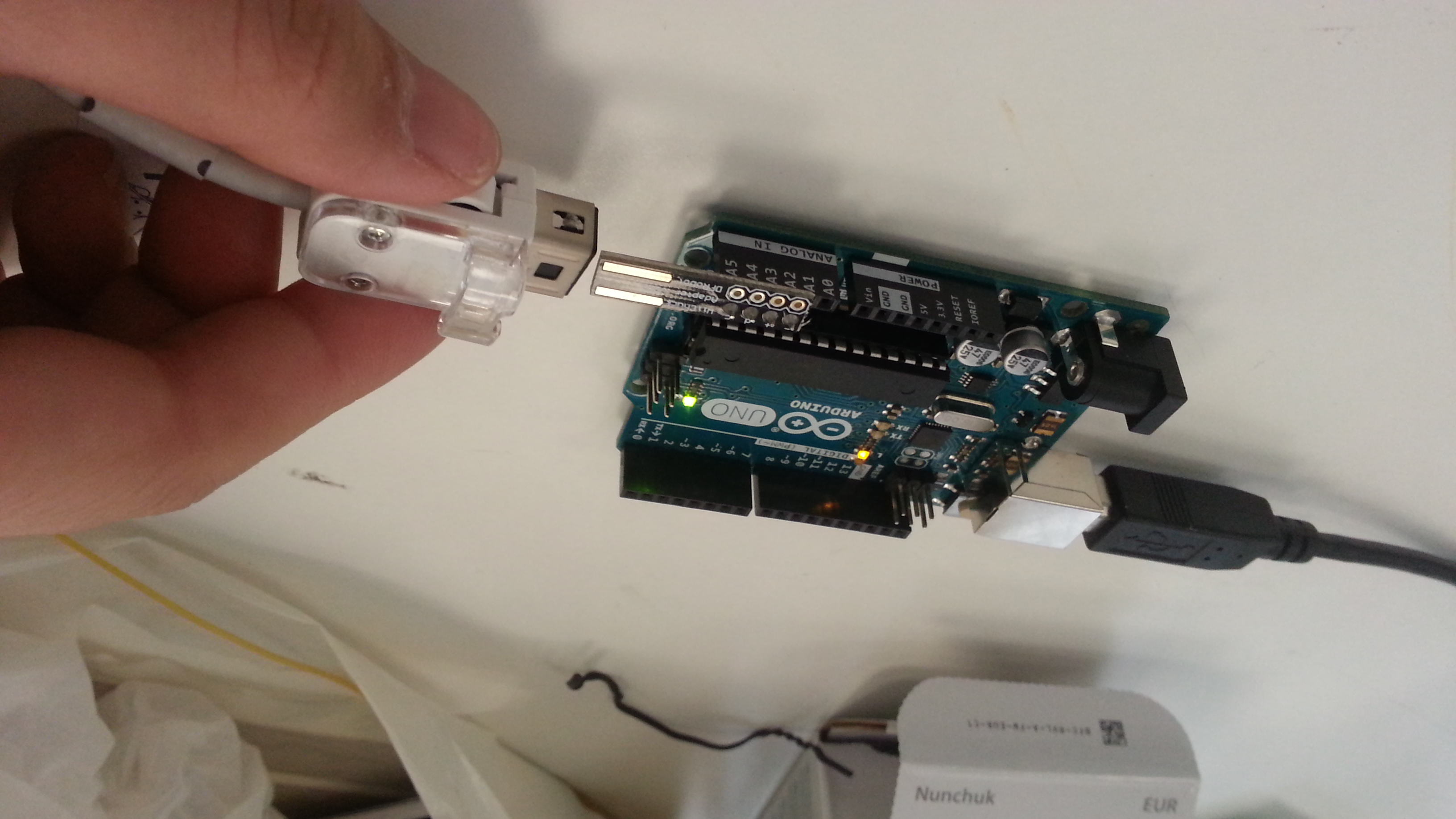
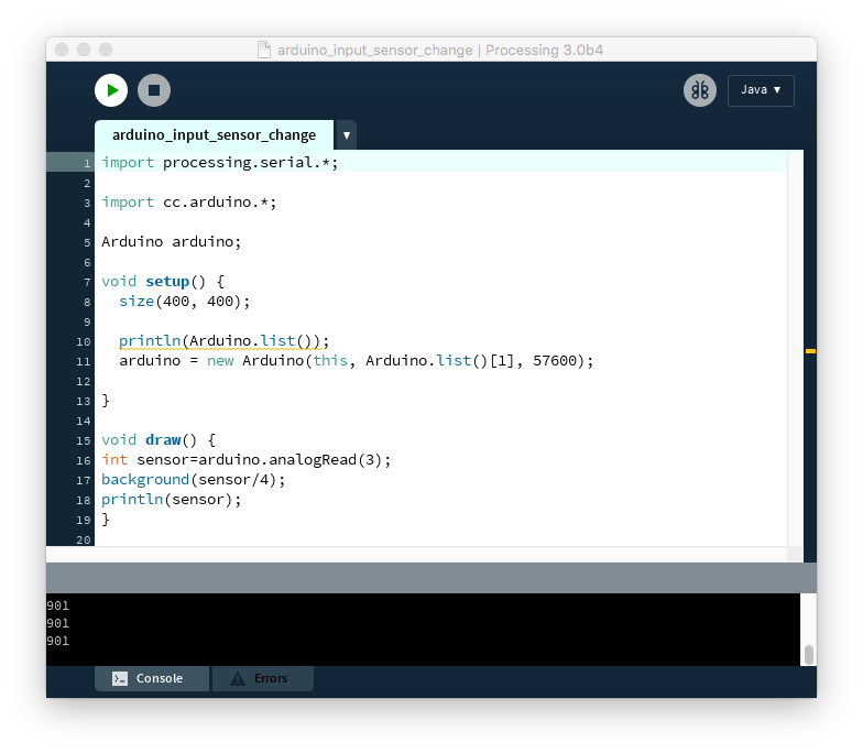
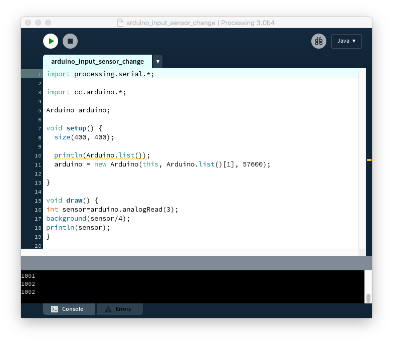
I only used the Processing coding language for this project. I created a series of strings which included several poetry fragments in each string. Each line of poetry will be selected based on a number taken from the average pixel color taken from each image uploaded. For the code to work, you should upload all of the images you want into the data folder of the processing file in an array with files called “place0.jpg” etc– or you can rename it as you wish. The code runs through all of the images automatically and creates gifs and takes screenshots of what is generated from each image.

import gifAnimation.*;
import processing.opengl.*;

GifMaker gifExport;

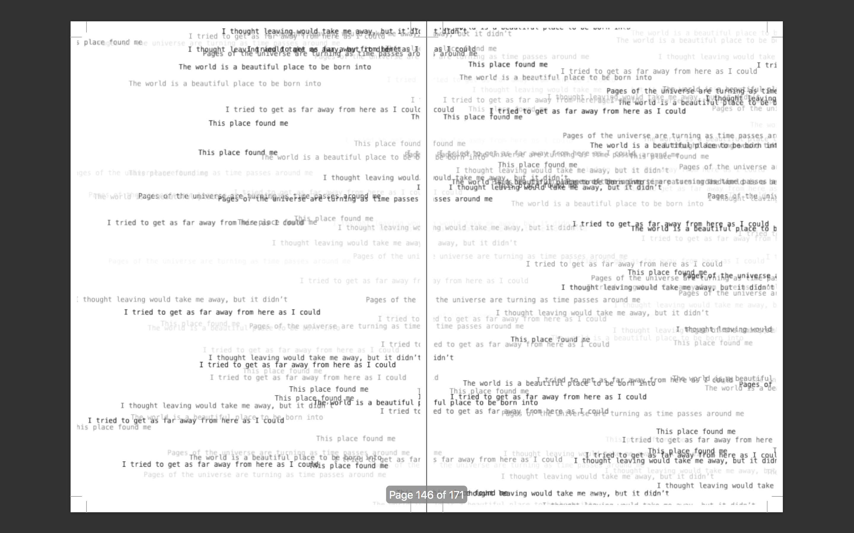
String [] firstWords = { “I’m homesick for places I haven’t been”, “Without even looking, you can see that”, “It used to be dangerous here”, “The world is a beautiful place to be born into”, “On this street I’ve always known”, “I wish we could see the stars in this city”, “Walking down streets strange as these”,

}; String [] secondWords = { “Smells of this familiar place fill my nose”, “I thought I would have formed an idea of depth of the city”, “Golden dawn and shivering evening find us”, “I ran away and crossed mountains and forests”, “Waves crash onto concrete shores”, “Pages of the universe are turning as time passes around me”, “In the clouds and the sun”, “People here have funny faces”, “Smells of this unfamiliar place fill my nose”, “I can feel the flowers seeding under the concrete”,

}; String [] thirdWords = { “Comedy drips on the grass stages”, “As elegant as a Paris street, favored by light”, “I came here for sanctuary”, “I came here for release”, “Can we lay in the grass and tell our memories of each star”, “I thought leaving would take me away, but it didn’t”, “This place excites me”, “I came here for sanctuary”, “I came here for release”, “I came here to escape”, “I’m stuck in this waiting place”, };

String [] fourthWords = { “I came here to escape your memory” , “I can only pretend that your memory isn’t written all over these walls”, “It’s impossible to describe the opaque light”, “Meadows of flame leap up to the summit of the little hill”, “My breath like the wind on dead flowers”, “I tried to get as far away from here as I could”, “I think I can see you in the distance”, “Meadows of flame leap up to the summit of the little hill”, “My breath like the wind on dead flowers”, “I tried to get as far away from here as I could”, };

String [] fifthWords = {

“These feelings are all in my head”, “Yet I come here to forget”, “Yet I come here to remember”, “This place found me”, “Will you join me to watch the sun rise over the ocean?”, “I feel at home here” , “I’m still not welcome”, };

PFont menlo; PImage img;

String[] imageList;

int currentIndex = 36;

void setup(){

size(1200,800, OPENGL);

frameRate(15);

background(255);

menlo = createFont(“Menlo”, 12);

textFont(menlo);

println(color(0));

println(color(255));

imageList = listFileNames(“place”);

img = loadImage(“place”+ currentIndex +”.jpg”);

println(“gifAnimation ” + Gif.version());

gifExport = new GifMaker(this, “place”+ currentIndex +”.gif”);

gifExport.setRepeat(0);

}

color getAverageColor(PImage img) {

img.loadPixels();

int r = 0, g = 0, b = 0;

for (int i=0; i>16&0xFF;

g += c>>8&0xFF;

b += c&0xFF;

}

r /= img.pixels.length;

g /= img.pixels.length;

b /= img.pixels.length;

return color(r, g, b);

}

String[] listFileNames(String place) {

File file = new File(place);

if (file.isDirectory()) {

String names[] = file.list();

return names;

} else {

// If it’s not a directory

return null;

} }

void draw(){

fill(random(255));

int avgColor = getAverageColor(img);

int word1index = (int) map(avgColor, -16777216, -1, 0, firstWords.length); int word2index = (int) map(avgColor, -16777216, -1, 0, secondWords.length);

int word3index = (int) map(avgColor, -16777216, -1, 0, thirdWords.length); int word4index = (int) map(avgColor, -16777216, -1, 0, fourthWords.length);

int word5index = (int) map(avgColor, -16777216, -1, 0, fifthWords.length);

String word1 = firstWords[word1index];

String word2 = secondWords[word2index];

String word3 = thirdWords[word3index];

String word4 = fourthWords[word4index];

String word5 = fifthWords[word5index];

text(word1,random(0, 1200),random(0, 1200));

text(word2,random(0, 1200),random(0, 1200));

text(word3,random(0, 1200),random(0, 1200));

text(word4,random(0, 1200),random(0, 1200));

text(word5,random(0, 1200),random(0, 1200));

gifExport.setDelay(1);

gifExport.addFrame();

if (frameCount % 50 == 0) {

// Add a new frame to the gif

saveFrame();

println(“frame saved”); }

if (frameCount % 150 == 0) {

// Save the ongoing gif, create a new one, clear the screen, load the next image and analyse it

gifExport.finish();

println(“gif saved”);

background(255);

currentIndex++;

img = loadImage(“place” + currentIndex +”.jpg”);

gifExport = new GifMaker(this, “place”+ currentIndex +”.gif”);

gifExport.setRepeat(0);

println(currentIndex);

//if (currentIndex++ == imageList.length) {

// exit();

//} } }

place00

^click on the gif!


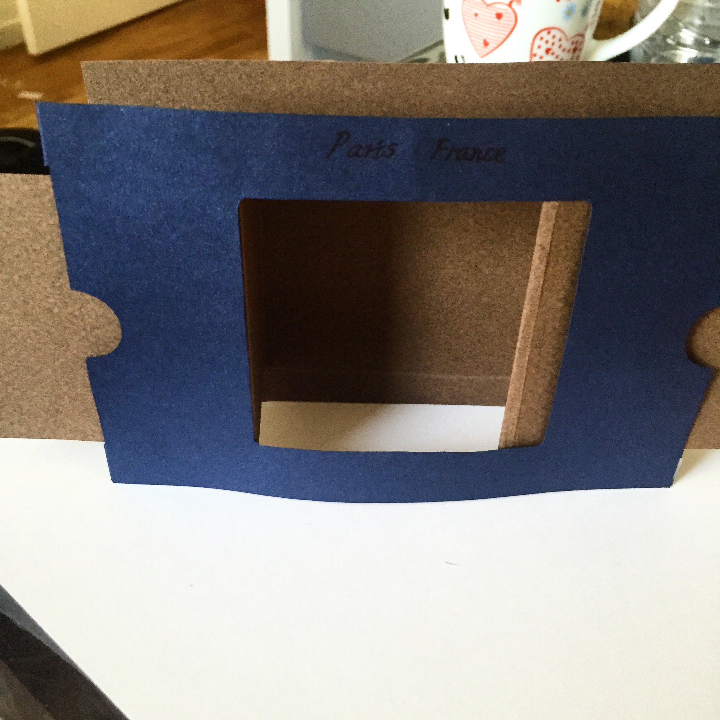
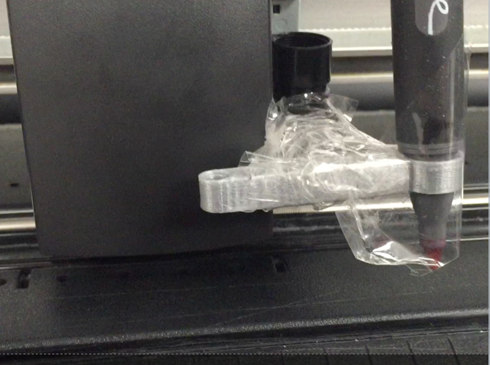
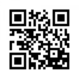
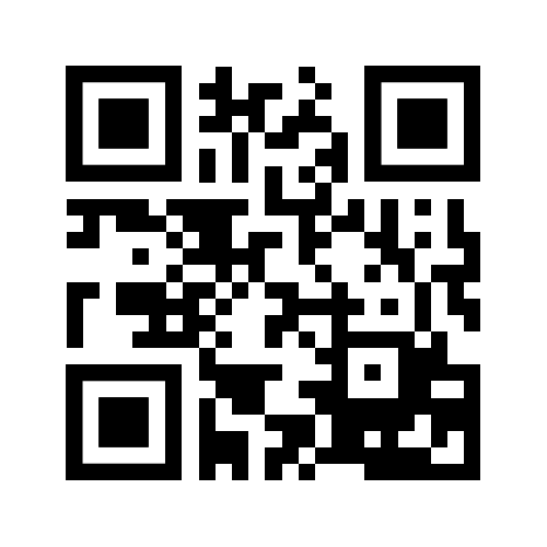
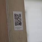
One thing I really wanted to do with this project was give my generated poetry back to the places I used to create it and not just keep it for myself. I decided using QR codes would be a cool way to do this, as I could upload the GIFs of the poems generating and make it visible, which it isn’t in my documentation of the project (I made a book of poetry). I created them through an online generator at www.qr-code-generator.com . I printed these QR codes onto adhesive paper and made stickers with them, so I can stick them wherever I wish. Obviously in a city they are easier to apply, but it’s the idea that counts–you could take the poems back to nature in other ways too, like writing them in the dirt or sand or with a sharpie on rocks. Scan my code I uploaded and see how it works!

Screen Shot 2015-12-15 at 10.02.35 PM                           dashatournelle


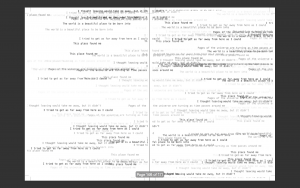
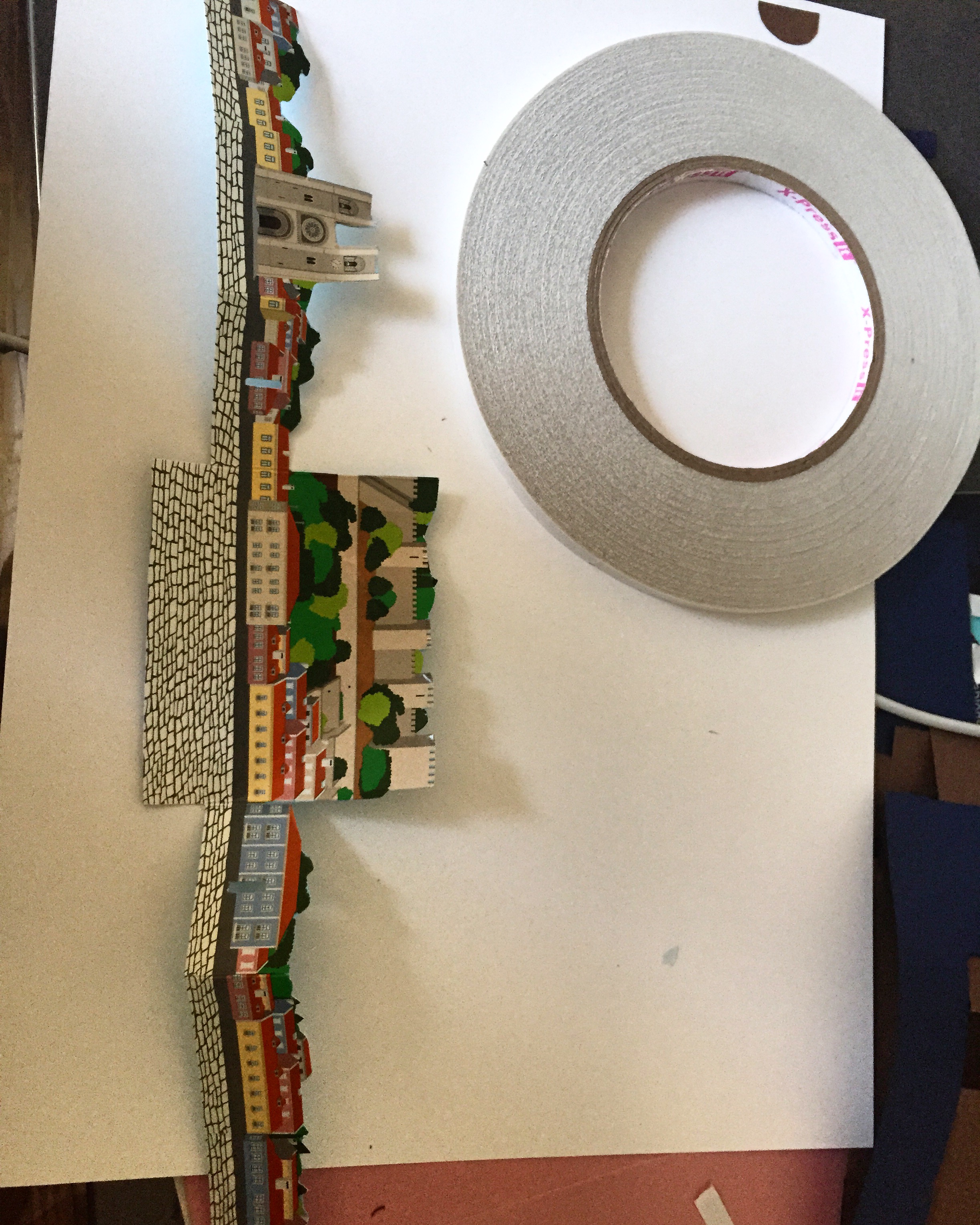
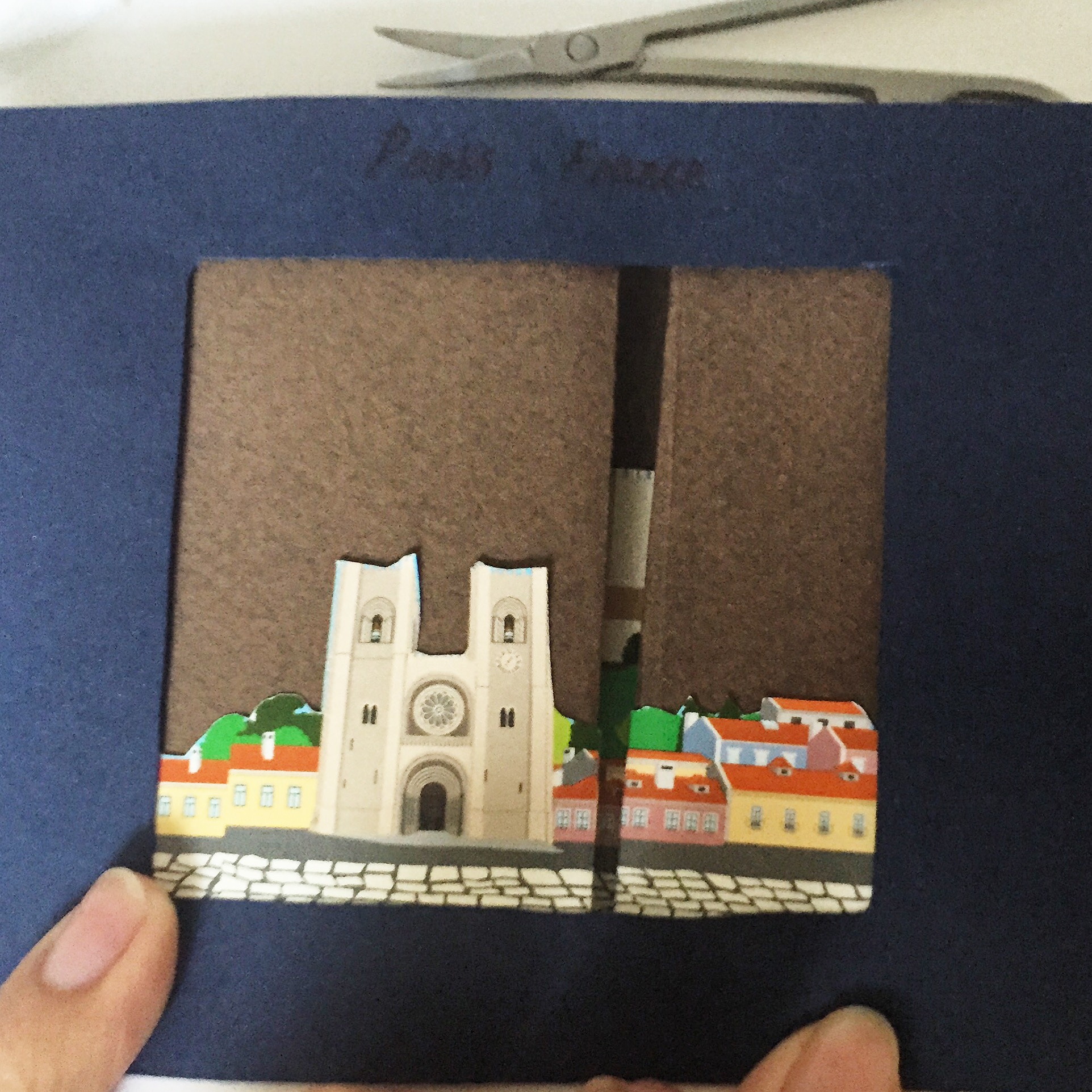
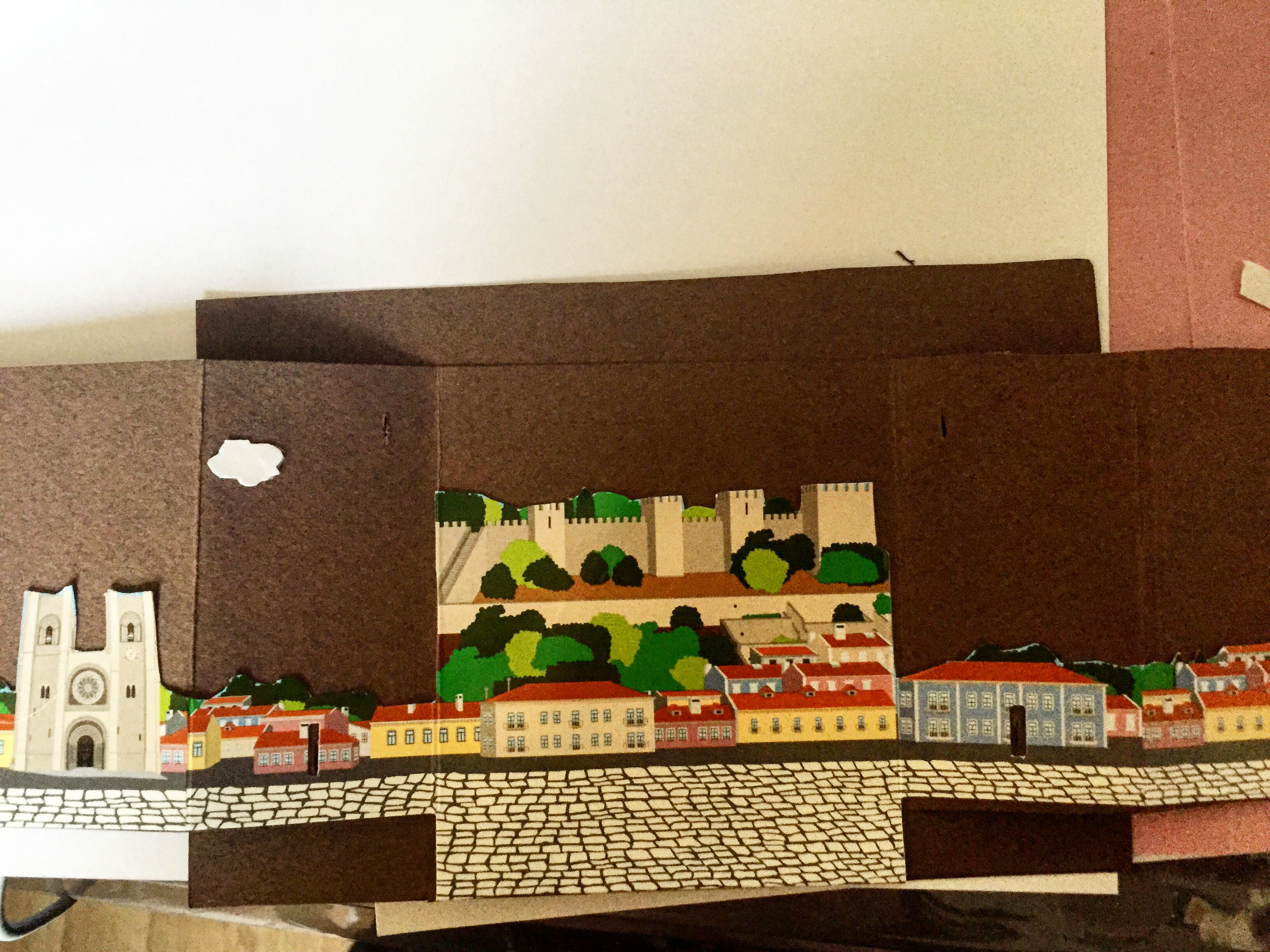
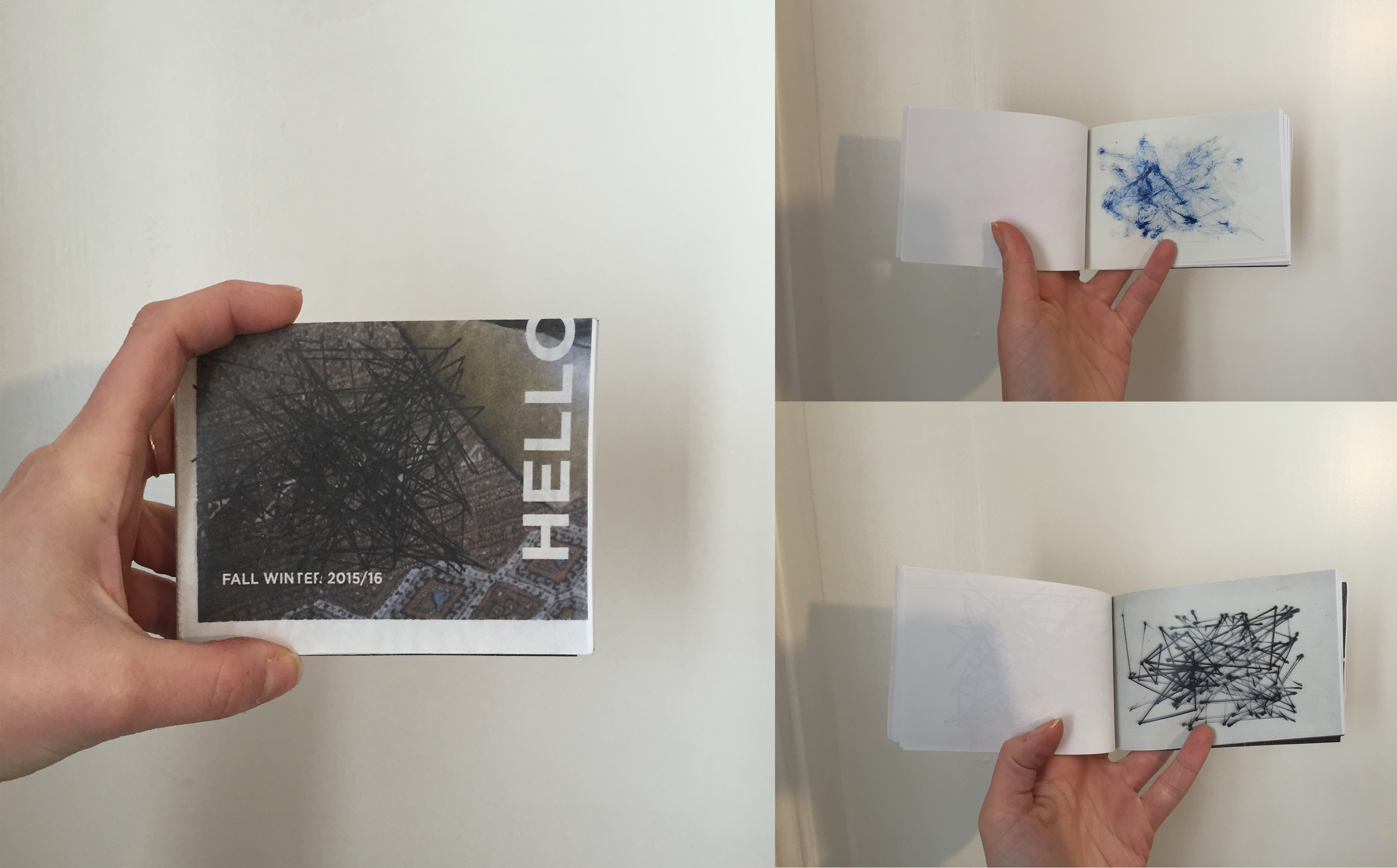
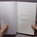
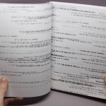
As poetry is traditionally printed, I decided to take this project full circle and bring it back to its roots and make a book of poetry and the photos which were submitted. I used the screenshots from each poem, the image, the place, and the QR code. My book ended up being 171 pages because I had lots of nice images given to me. This example was a photo that I took, but I credited each person who submitted images as well. I made the layout using InDesign, and printed copies in both black and white and color. Personally, I preferred the black and white print more, but that’s just me.

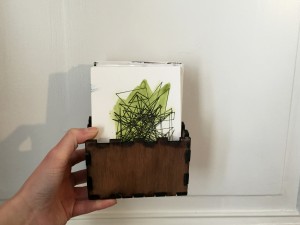
I printed this copy on a normal black inkjet printer and bound it with glue using a bookbinder–you can also find binding glue at any craft store and do it at home. The book is a little smaller than an A5 size, and I ended up printing six copies. Also stick up your QR codes so everyone can enjoy!


Abstract C_ /// A Drum Clock

20151216_213843

Music has always been of great inspiration to me, as well as the concept of time.

My project is about trying to make an abstract clock with a drum set. Abstract because it will play every hour, but you won’t actually know what hour it is.

The idea is to have different elements (drum sticks, mallets, brushes, solenoids…) hitting the drums, driven by step motors and arduinos. The objects would start playing a random sample by hour. I plan to use a lamp timer to activate the arduino and launch the code every hour.

So far, I’ve been trying to get the motors to work, but they are not running on 12V, only 5V, which doesn’t give them enough force to hold the drumsticks.

  20151207_224653  20151207_230320-2

After figuring out that the motor shield didn’t work, I set up to build my own. That way, I could control 4 motors with pololu motor drivers and 1 single arduino.

20151209_192453 20151208_155239

The structure is made with a metal L on top of which I screw the motor. They’re tighten around the screw of the drum with a little structure that allows is to be stable.

20151215_181436 20151214_100058 20151215_164403

I pierced a hole in the drumsticks to put them on the axis of the motors, and found different ways to counterbalance them (if they’re not counter balanced, they don’t come back once they hit the drum):

20151216_114330 20151216_10310720151215_222954

It ends up looking like this:

20151216_213843


The code is simple enough. I used the Accelstepper library on Arduino, which allows to control not only the speed but also the acceleration of the motors. That way I had different variables to play with.

#include <AccelStepper.h> // Utilisation librairie Accelstep, déclaration des moteurs
//AccelStepper M0(A5, A6, A7);

AccelStepper M0(1, 3, 2), M1(1, 5, 4), M2(1, 7, 6), M3(1, 9, 8); //step,dir

//instead of calling M1(1,3,2)
AccelStepper M[] = {M0, M1, M2, M3};
int ms1 = 12 , ms2 = 11, ms3 = 10;; // déclaration des broches controlant le micro stepping (la valeur résultante est commune à tous les modules)
//int var = random (0,3);

int temps = 0;

int distance = 50;

int pos = 60; //number of steps (one revolution = 200)

int stopIt = 0;

void setup() {
// put your setup code here, to run once:

pinMode(ms1, OUTPUT);
pinMode(ms2, OUTPUT);
pinMode(ms3, OUTPUT);
digitalWrite(ms1, LOW);
digitalWrite(ms2, LOW);
digitalWrite(ms3, LOW);
}

void loop () {
// M[1].setMaxSpeed(20000);
// M[1].setAcceleration(80000);
// M[2].setMaxSpeed(10000);
// M[2].setAcceleration(500);
// M[3].setMaxSpeed(8000);
// M[3].setAcceleration(2000);
for (int h=0; h<5; h++) {

M[1].setMaxSpeed(random (10000, 20000));
M[1].setAcceleration(5000);

M[2].setMaxSpeed(random (20000, 50000));
M[2].setAcceleration(random (500,5000));

M[3].setMaxSpeed(random (10000, 40000));
M[3].setAcceleration(random (500, 5000));

delay (50);

//the Move function tell the motor the distance it will have to run
M[1].move(50);
M[2].move(70);
M[3].move(70);

//the run function makes the motor move to the distance set with move()

while (M[1].distanceToGo() > 0){
M[1].run();
}
while (M[2].distanceToGo() > 0){
M[2].run();
}
while (M[3].distanceToGo() > 0){
M[3].run();
}
delay (50);

//Set the motors to hit, then go back to their original position:
M[1].move(-50);
M[2].move(-70);
M[3].move(-70);

while (M[1].distanceToGo() < 0) {
M[1].run();
}
while (M[2].distanceToGo() < 0) {
M[2].run();
}
while (M[3].distanceToGo() < 0){
M[3].run();
}

}

delay(900000); // 15 minutes is the time the lam programer stays on. The delay is set so that
//it doesn’t keep playing for 15 mn.

}


Because the motors end up having different behaviors than expected (probably a problem in the shield I built), the clock turns out to have some sort of life of its own.
I wanted to produce a series of rhythmic samples that would randomly be activated every hour. That turned out to be impossible given the autonomous rebel behavior of my motors.
In a way, I prefer having it this way. It feels as if it has a life of its own and the capacity to make its own decisions, and I created some kind of Frankenstein.


Instructables Link to build your own: http://www.instructables.com/id/AbstractC-a-Drum-Clock/

Here is a small video of what it looks like:


SICK BEATZ//MAD STEPZ (final project by Dasha and Sanie)

Link to the Instructables tutorial, for a more thorough description on how to make this happen.

Here is a tutorial on how to make a staircase musical instrument that makes sick beatz and produces generative art.

First, we had to make pressure sensors that would serve as the buttons of our musical instrument. We decided to make 4. For each sensor, we started with 2 pieces of neoprene and a piece of resistive fabric (25cm x 25cm each).

IMG_6903

You will also need two small pieces of conductive fabric to connect snap buttons and wires to.

IMG_6906

The first step after preparing the materials is sewing with conductive thread. We made parallel lines throughout both pieces of neoprene fabric.

IMG_6907

IMG_7168

Next step is to place the resistive fabric in between the two layers of neoprene with conductive thread, so that the parallel lines are going in different directions.

IMG_6942 IMG_6938IMG_6940

Then we attached to snap buttons to two corners (doesn’t matter which ones, as long as they’re not in the same corner) of the neoprene, that went through two small pieces of conductive fabric. The conductive fabric has to touch the conductive thread. We also connected wires to the snap buttons before the attachment that are then going to go to the lilypad.

IMG_6936 IMG_6937

IMG_7190

For more informations about how to connect the snap buttons, you can click here.

Once you’ve connected the wires you should test whether the sensor actually works. For that you first attach one of the wires to +, and another one to a 10K resistor and to -, and to an analog pin (A). You can see how it’s don in the scheme below:

scheme

To check that it works you can use the code seen in the photo below (if it works the values on the bottom of the screen in the console will change when you press the pressure sensor). You can copy it from this window or find it in processing examples called “arduino input sensor change”:

Screen Shot 2015-12-07 at 16.00.46 Screen Shot 2015-12-07 at 16.00.33

Here come the last steps: add foam on top of the sensor, once you’re sure that it works, and cardboard or thin wood on the bottom just to make it sturdy on the bottom.

IMG_7172

Lastly, find any fabric you like and cut out two 30x30cm squares to cover the foam, wood and pressure sensor. Make a whole in the fabric that the wires would go through and sew it all together!

IMG_7176 IMG_7179 IMG_7187

IMG_2343

IMG_2363

IMG_2367

IMG_2366

The finished result will look something like this:

IMG_2371

Then repeat all of the steps 3 more times to create 4 identical pressure sensors.

The code for Processing can be found on GITHUB. Add the data .wav files to the sketch, if you want to use our tracks. For Lilypad use All Inputs Firmata example code.


Final Project: LED Wall Garland

For my final project, I first thought I would be creating a three dimensional wall art piece incorporating simple LED lights as well as different types of LEDs; a light sensor, a microphone sensor for detecting sound, and a timer circuit. I actually did create the main elements out of paper, and also utilized copper tape and coin cell batteries to create successful connections to the LEDs, but my final idea was a little different from my original.

I  found inspiration through Jie Qi’s art works that incorporate paper and electronics, for example this pop-up book shown to me by Martin (thanks, Martin!):

And the living wall made in the MIT media lab:

Here is my original idea:

These pictures are unfortunately not of the best quality, but the project on the right by artist Janice Caswell is serving as inspiration for my project. I will (and did) use paper, and other materials if it seems appropriate, to create my installation incorporating LEDs. I thought I would loosely create a web representing connections. This project is very individual, so it can be customized, but for the tutorial, I will be clearly explaining how to create the basis of a project like this. It is easily customizable.

I will keep updating on my process once I really get going-but right now I am waiting for my components to come in the mail-which will be very soon! It will be easier to map out exactly what I am doing once I have everything in front of me.

Update as of December 13, 2015-

So I tested the process of the string abstract technique, and I realized that since I will be utilizing copper tape to connect my LEDs. the technical aspect will not be hidden by my installation as the strings are too thin. So, I have decided to instead create a wall garland that will be easier for anyone to reproduce, and create on their own. It will feature shapes (right now I deciding on whether I should do triangles or circles) illuminated by the LED, which will be in between to sheets of paper. I will have designs on each lit-up shape, and right now I am thinking of constellations or images of the night sky.

I was really inspired by these garlands: http://miavril.bigcartel.com/products produced by Virginie Sannier-Dorémieux who is actually from Toulouse, France! I will not be sewing the garlands, but simply attaching fishing line or string between the shapes. I have already designed and engineered how it will all work, and now I just have to put it all together.


Here is how my final project all came together:

Originally, was struggling to come up with an idea to use with my LEDs. I knew I wanted to make something with lights, but I was not sure what. So, after researching more projects and seeing Jie Qi’s work with paper circuits and circuit stickers:FullSizeRender
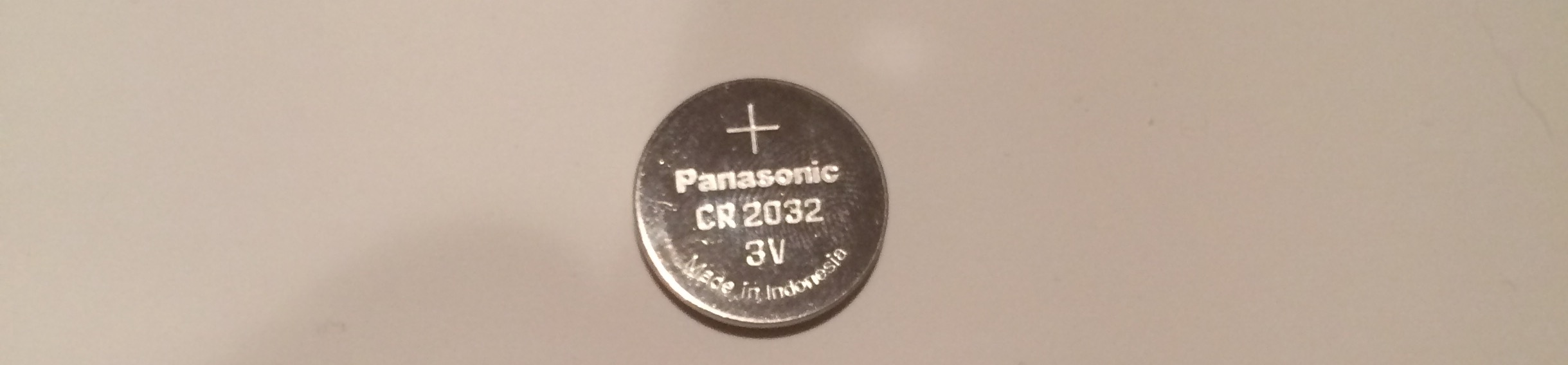
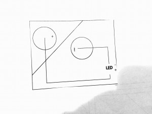
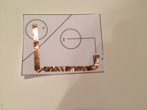
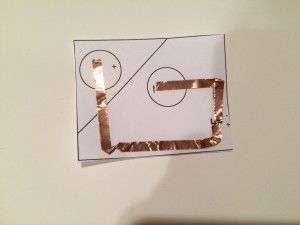
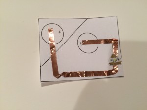
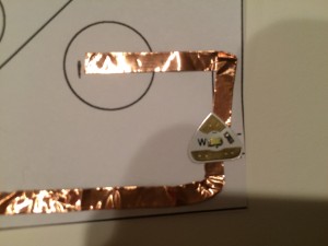
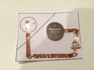
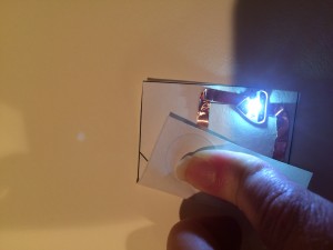
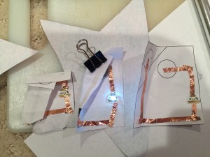
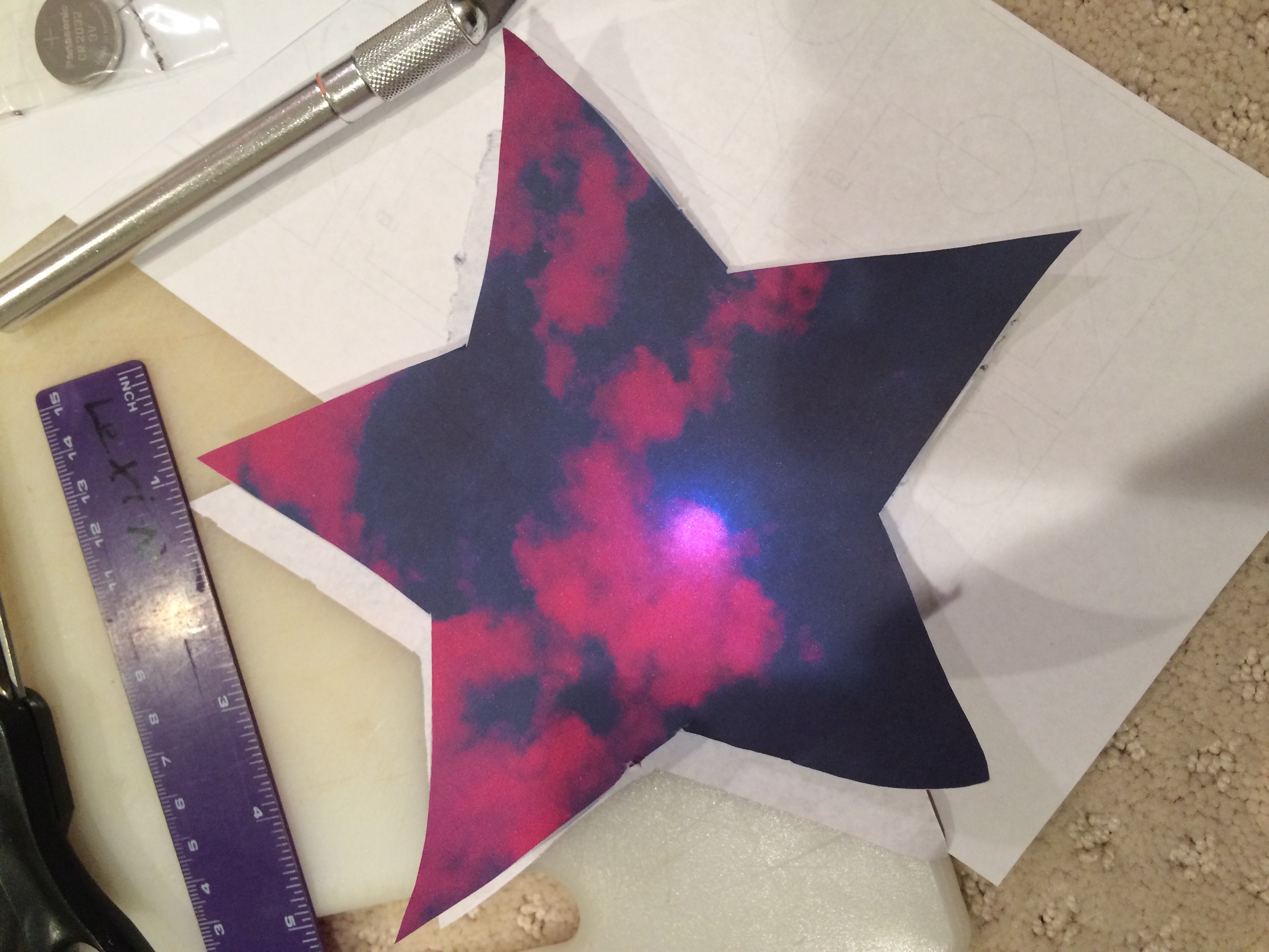
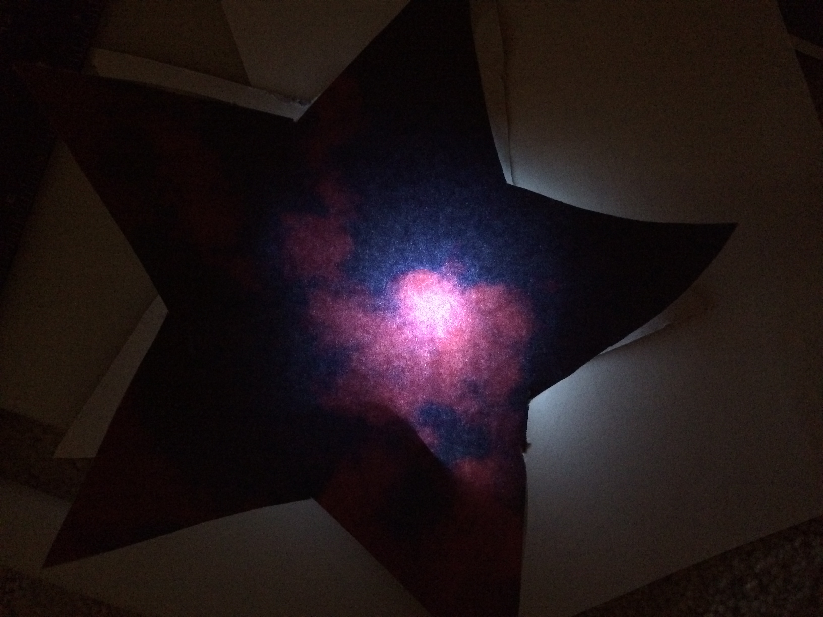
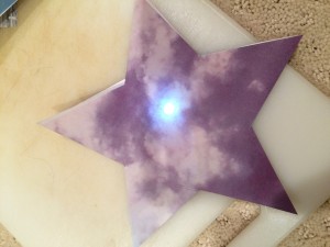
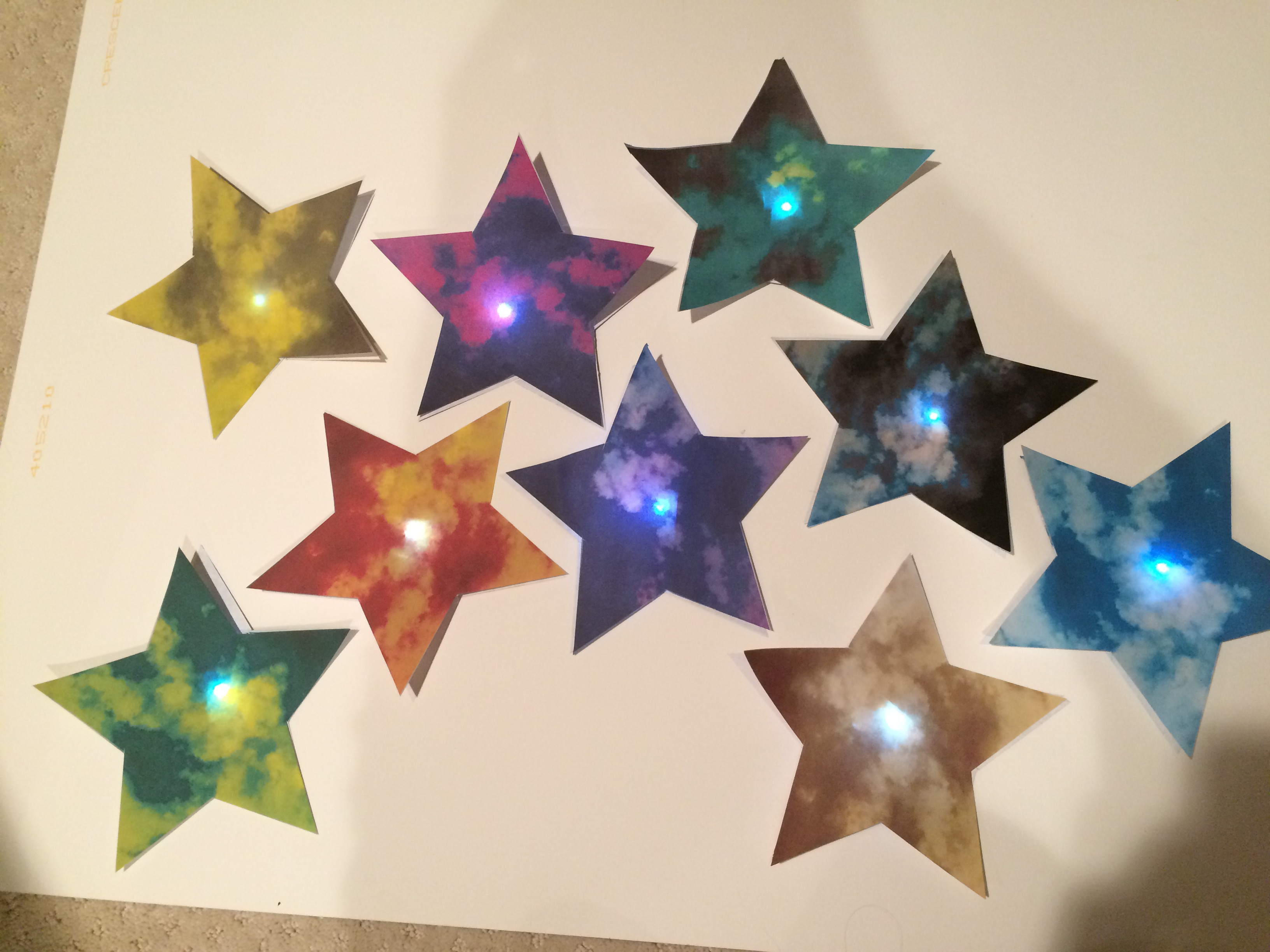
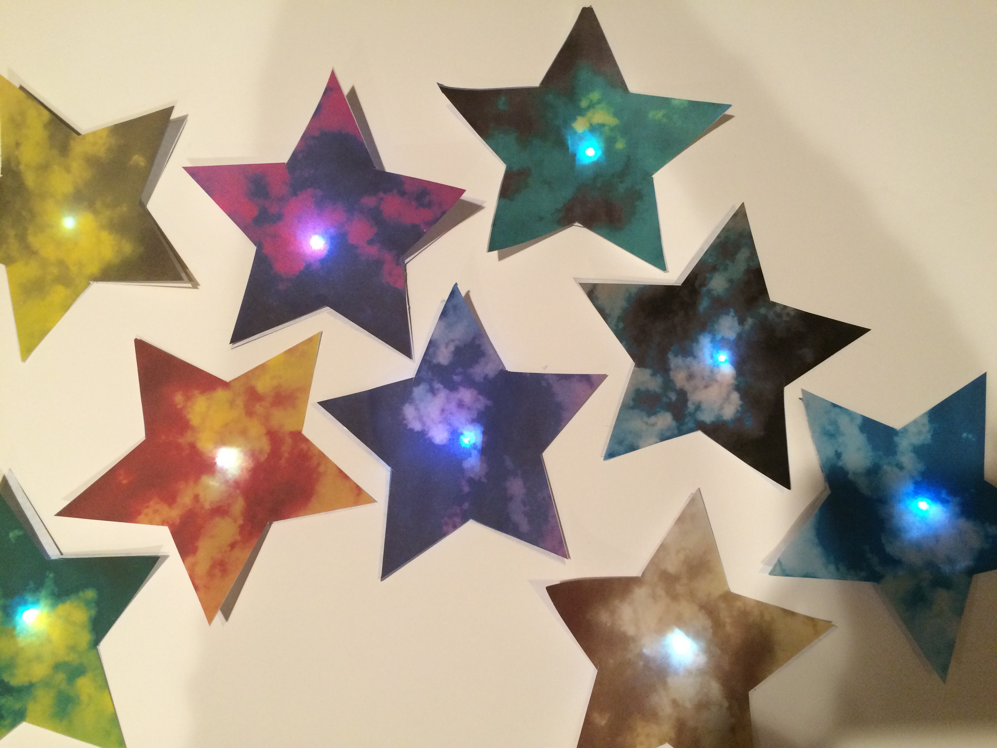
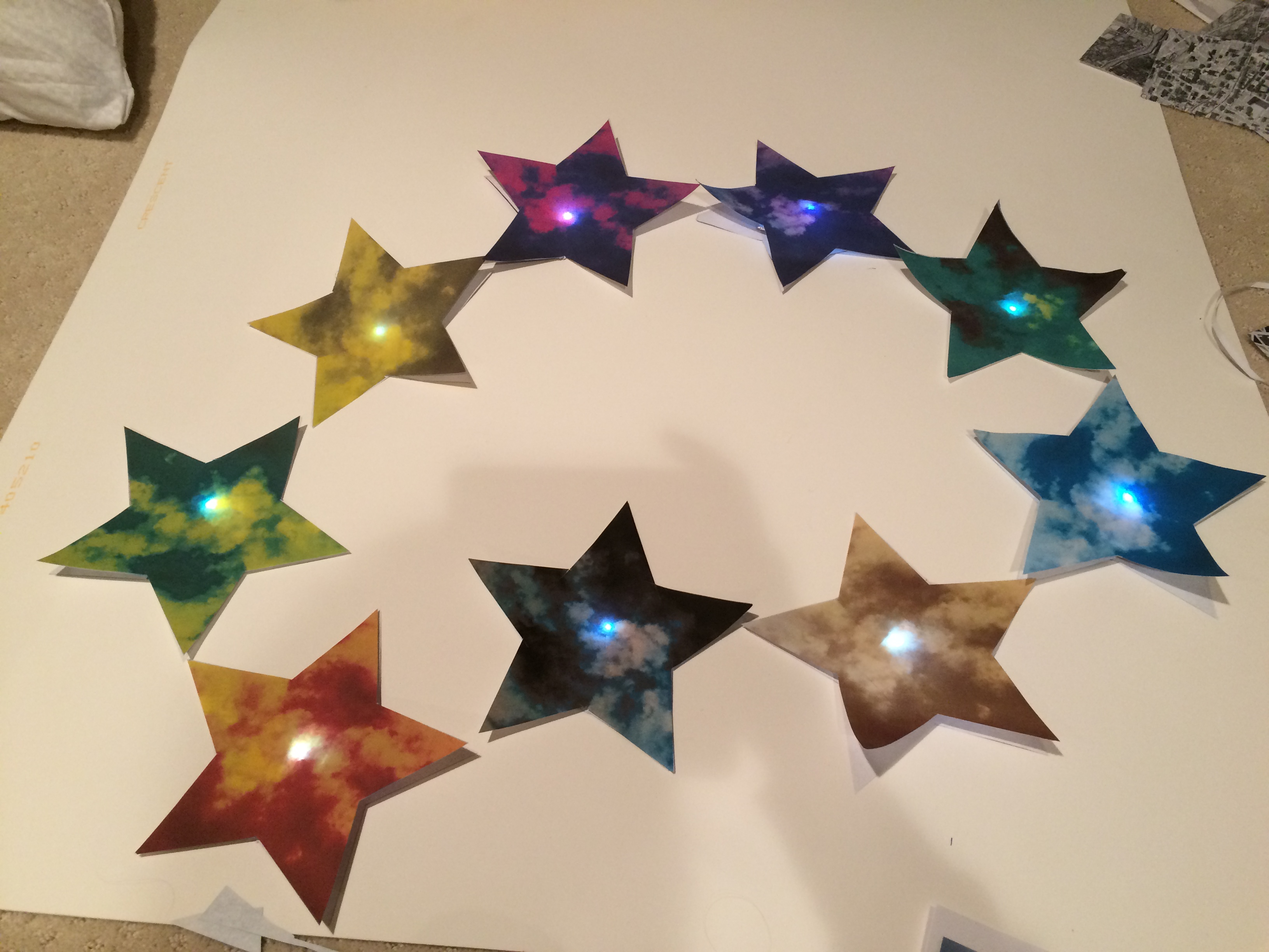
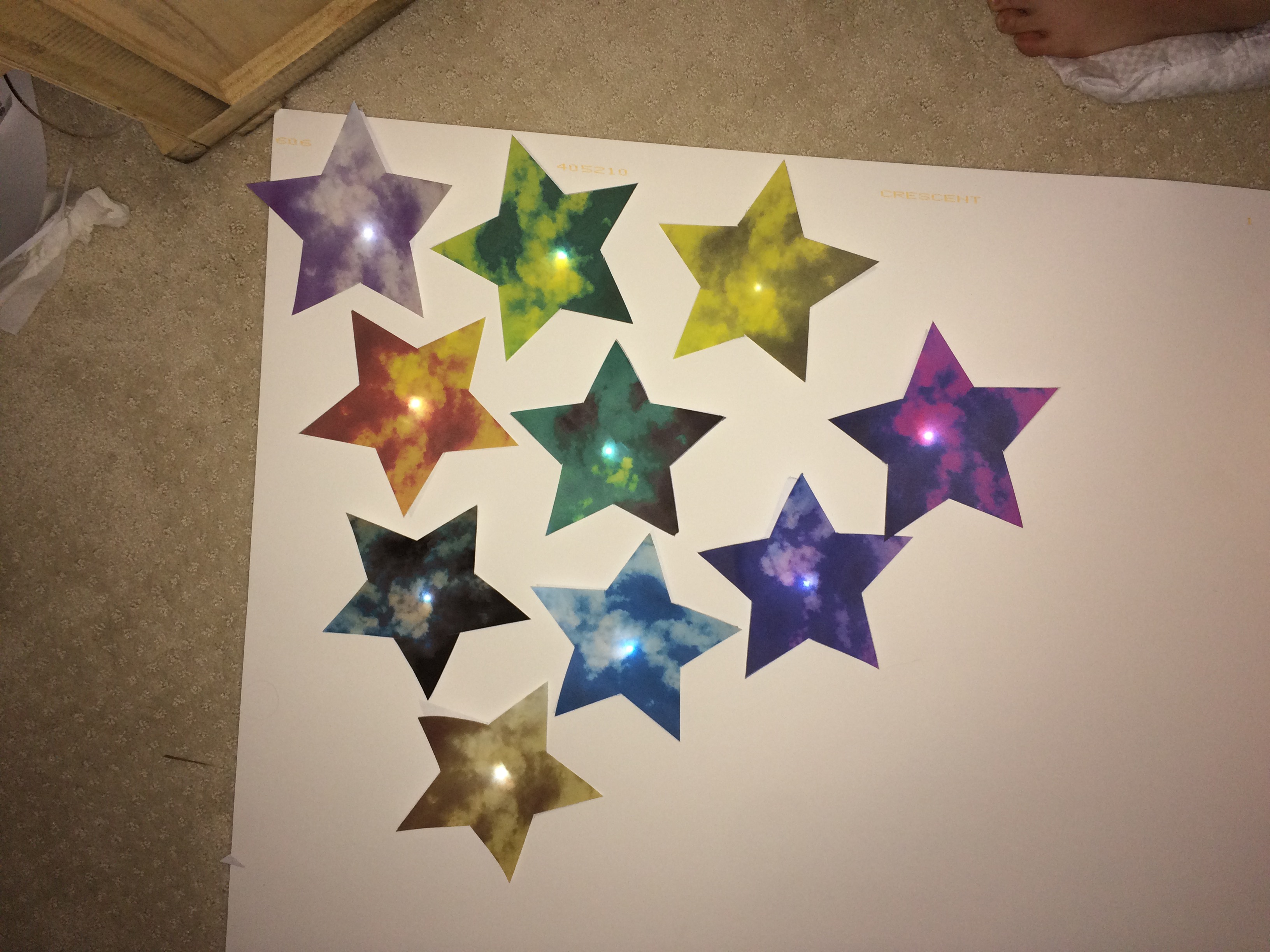
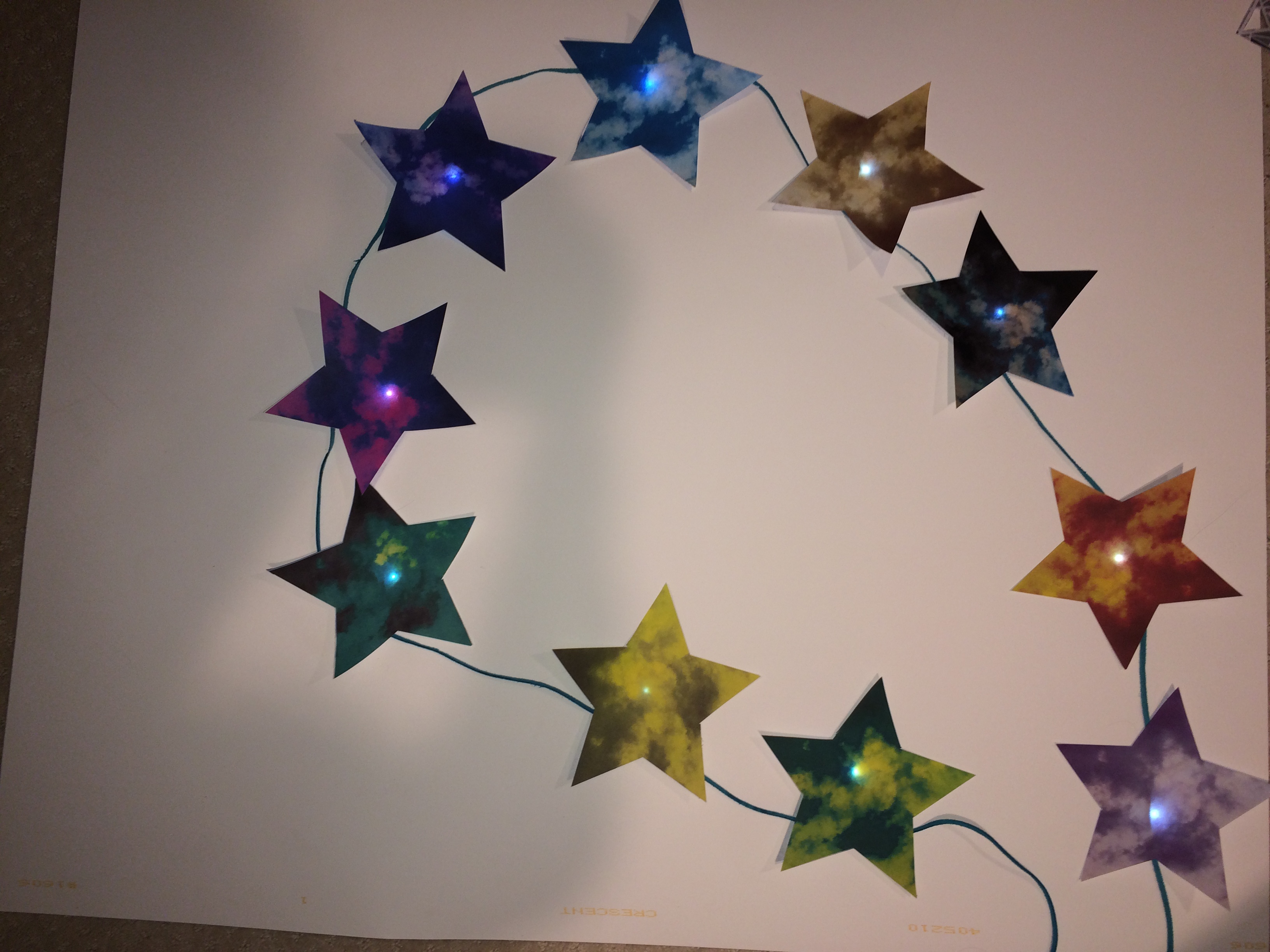
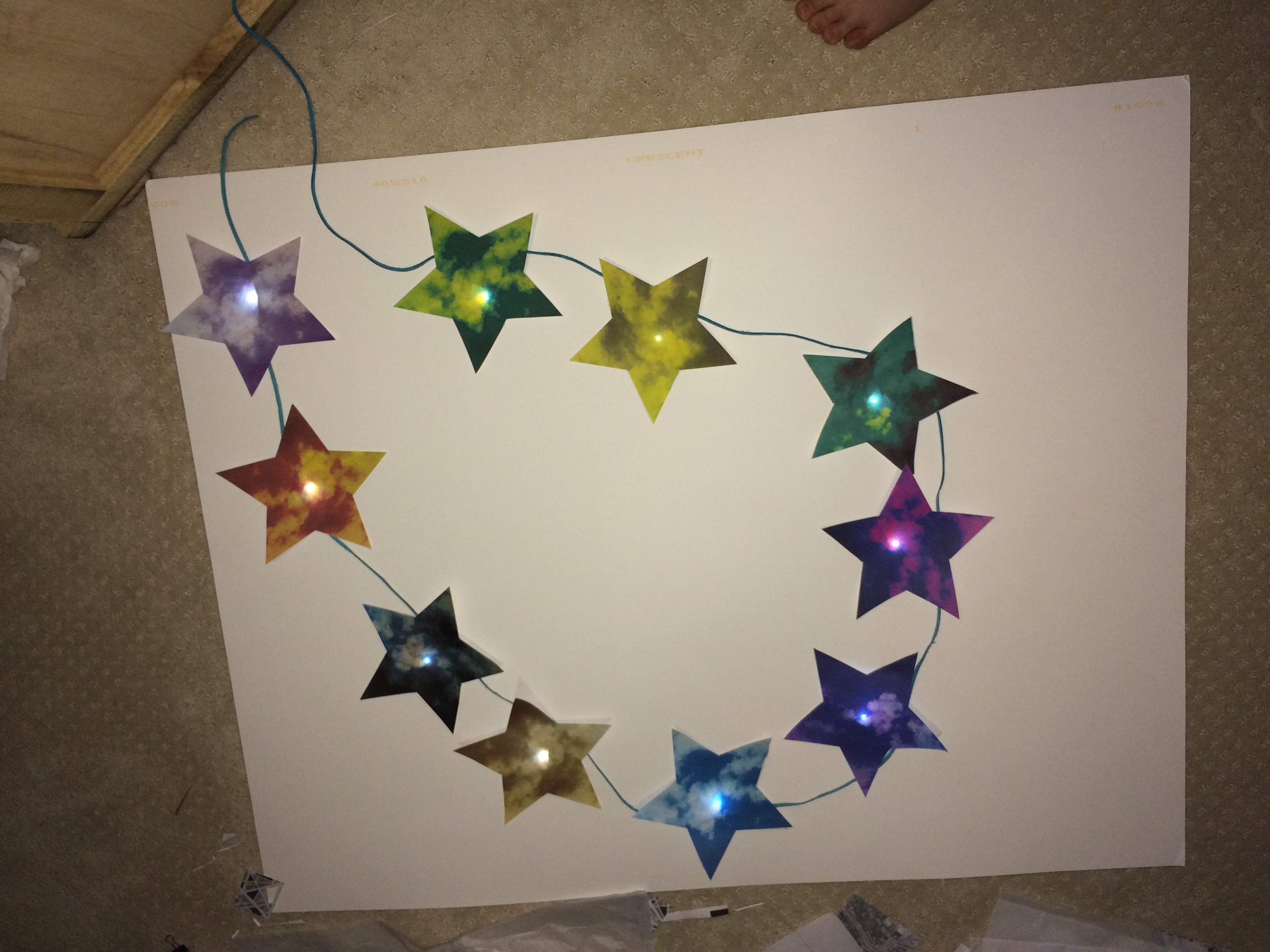
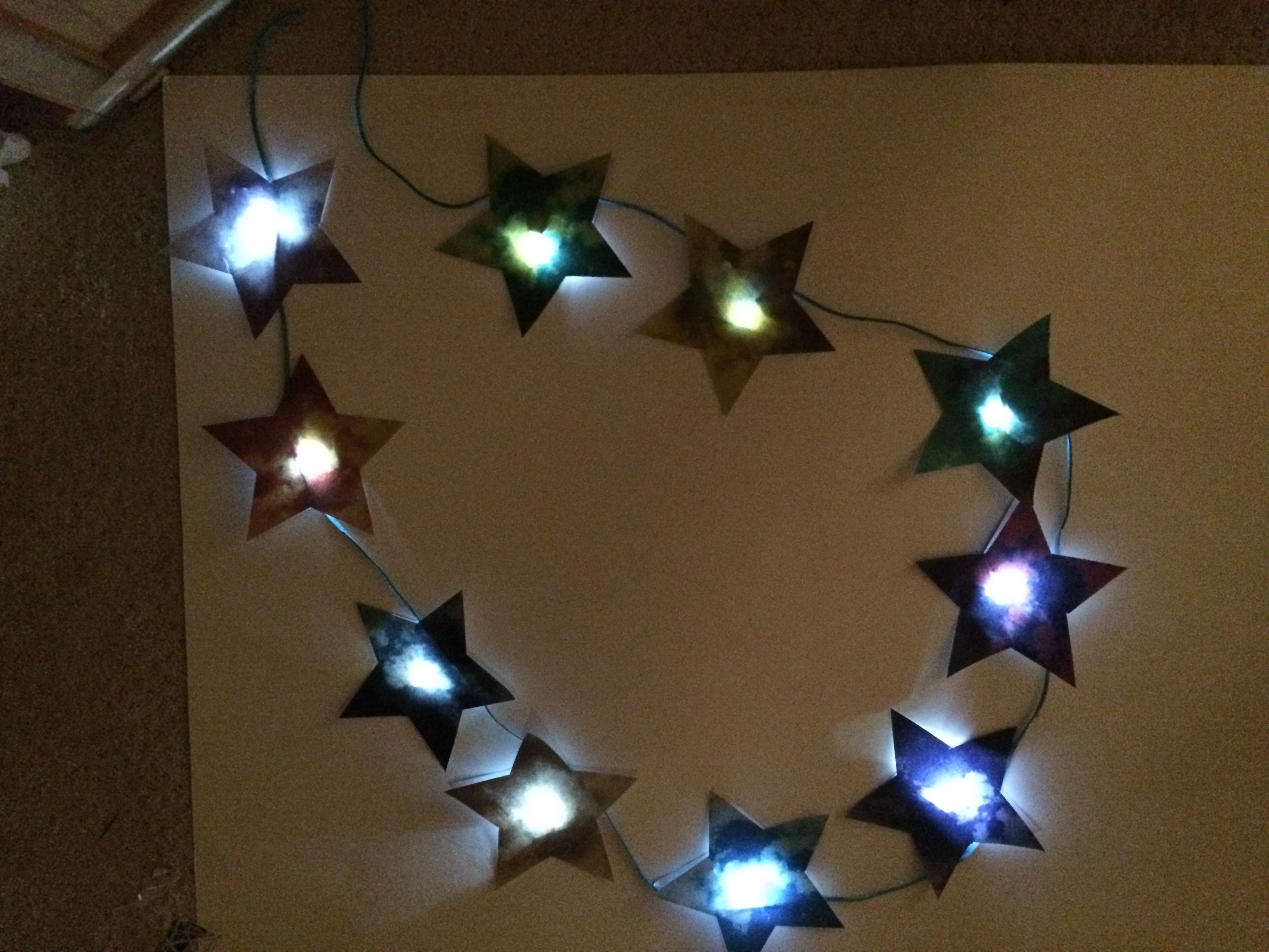
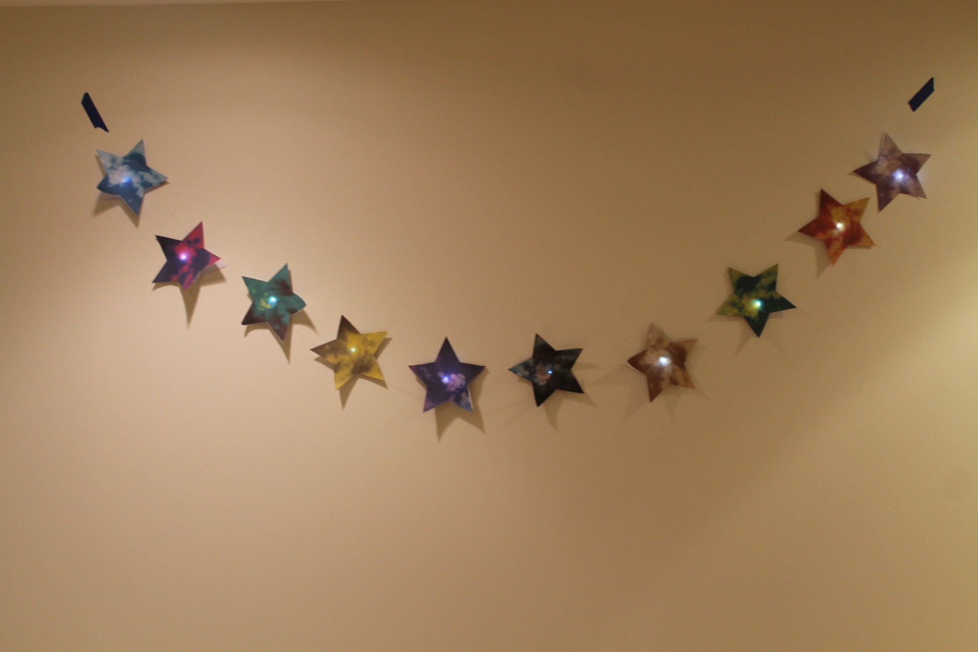
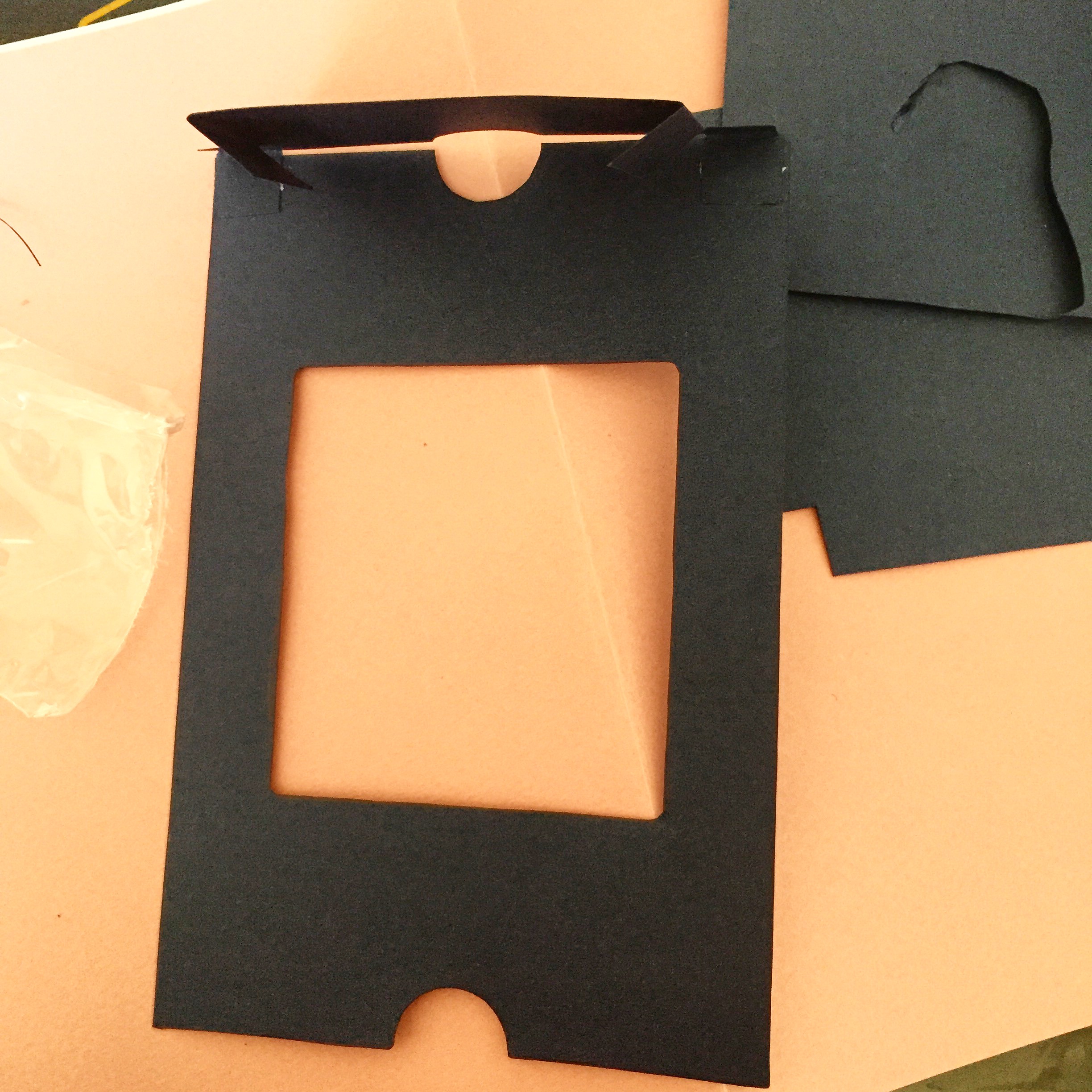
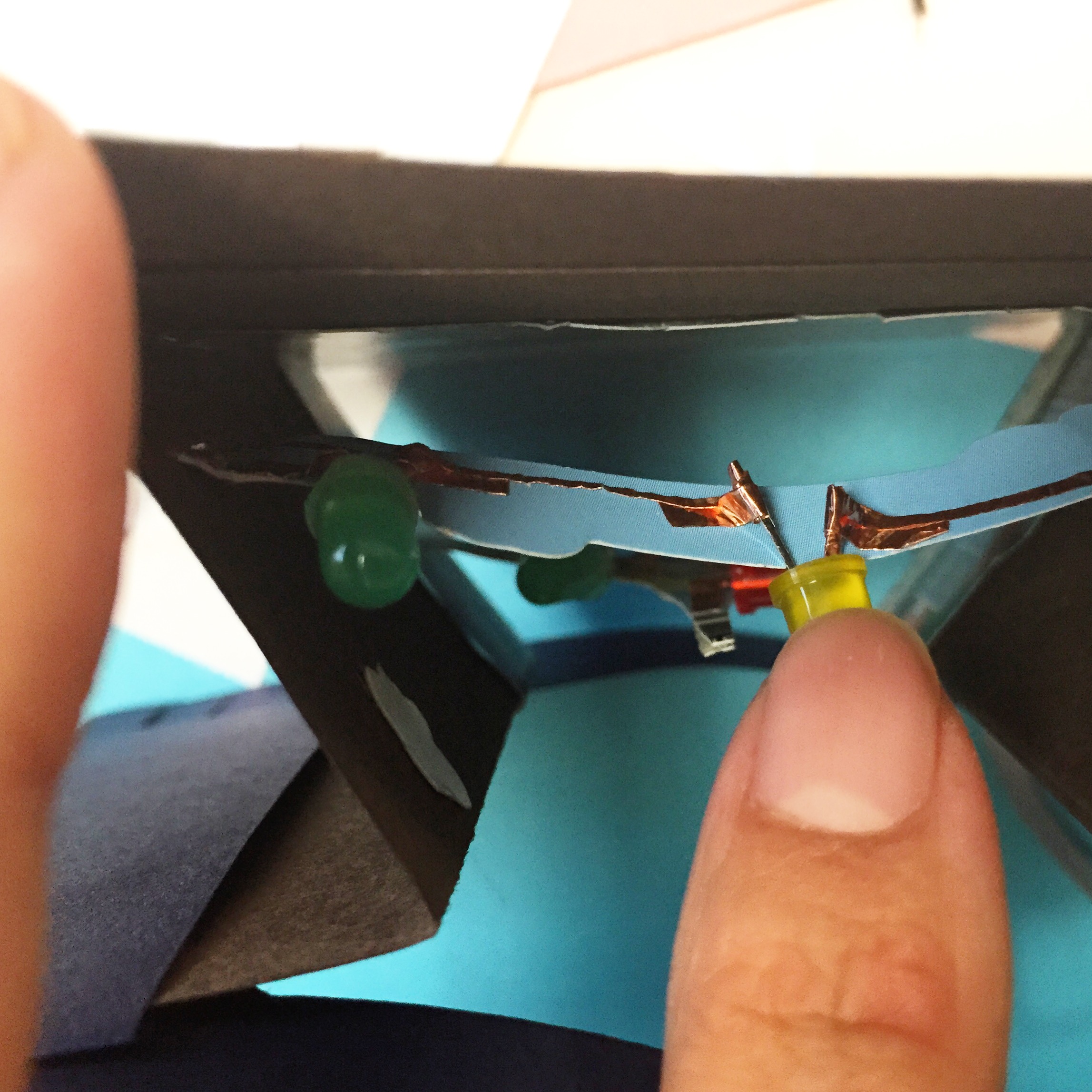
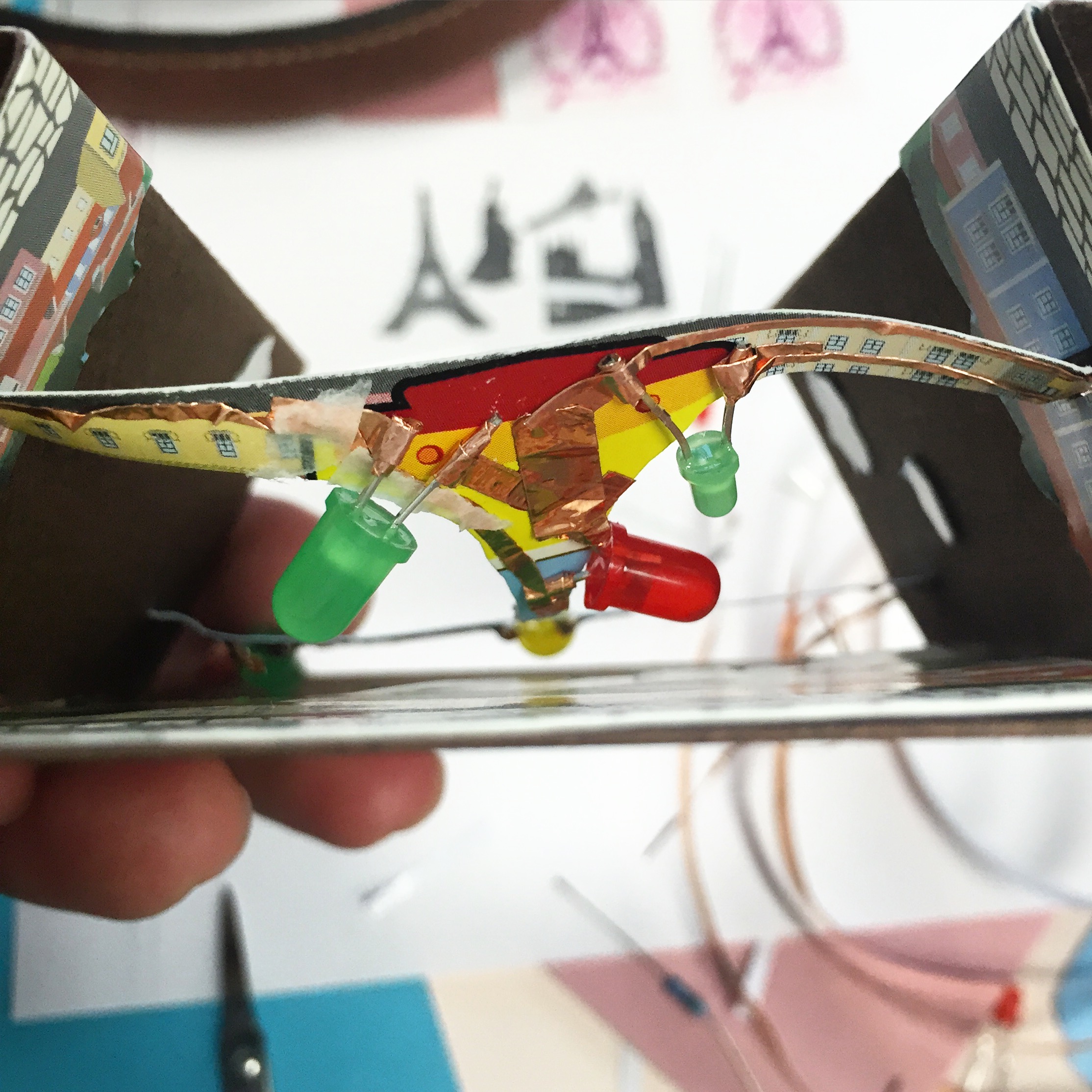
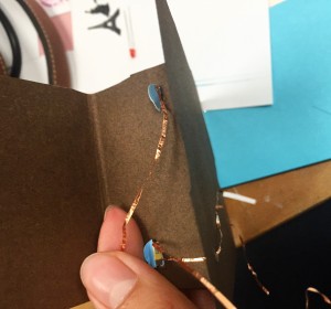
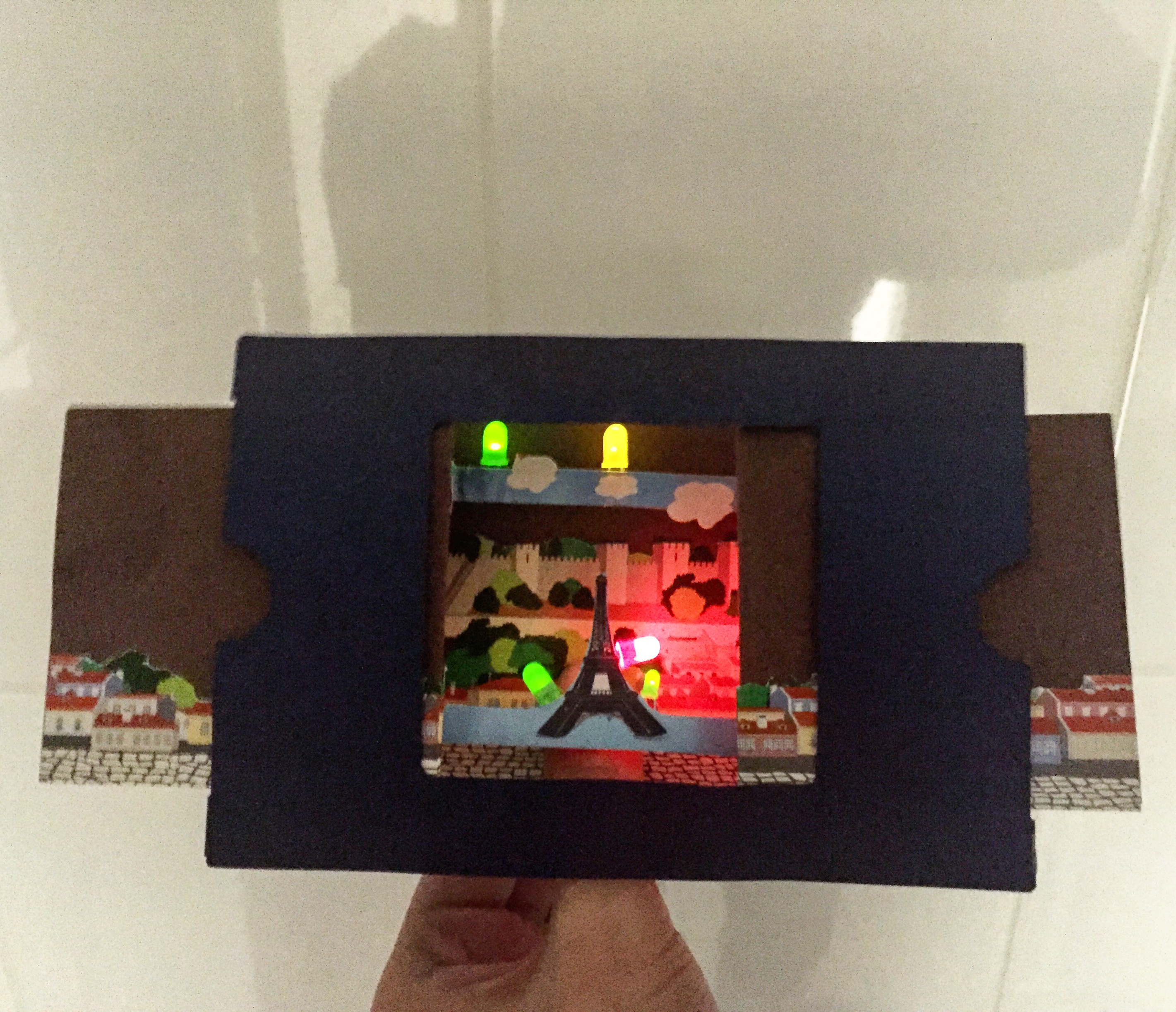
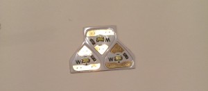
(http://technolojie.com/circuit-stickers/), I was inspired, so that’s how I came up with the idea of a paper star light-up LED garland. In order to make this, I ordered online LED stickers, 3 volt coin cell batteries, and copper tape. As soon as all my components came, I started to experiment, and made different connections, like this one:

IMG_4403

but I realized I did not know what I was going to make with this parallel circuit, and I knew I had to go simpler if I wanted to make something successful. So, I decided on the simple paper circuit LED. I created my own template that would fit inside my stars:

FullSizeRender 2IMG_4429

and used it inside all 10 of the paper lights I created. After getting the right size to fit inside the star shape, I developed my LEDs.

Placing the copper tape to create the correct connections, and then adding the LED sticker and battery:

IMG_4458IMG_4459
IMG_4460
IMG_4461IMG_4464

And then, I tested the connection by pressing on the battery, and most of the time, the circuit worked well. Some of the time, I realized I folded the copper tape too much or not as well as I could have, so the connection was weak. Then I just re-made the circuit, and learned from my mistake.IMG_4465

And then, after testing, I taped the battery into the circuit. Of course, soldering would have been the best way to affix the battery to the copper tape, but I do not have a soldering iron. Actually, at first, I was going to use a glue gun to glue the battery to the copper tape. But after researching this, I quickly learned that because the glue is hot, it weakens the connection and is a horrible way to connect circuits! So, I decided on tape. I made sure it did not touch the copper tape as the strongest tape I found turned out to be silver. Like I said before, I would have preferred to solder, but this was the only option for me as I am working from home. However, the tape worked extremely well and provides an excellent way to keep the battery in the circuit.

So I decided to make 10 stars, so I had to make 10 paper circuits. I ended up with around 14 because some were having issues, or stopped working. And before I even came up with the official circuit, I had many prototypes:

IMG_4428  IMG_4441

Next, after I tested and decided on an appropriate circuit for my stars, I printed out my multicolored stars and taped the circuit to them, using double-sided tape. I designed the stars myself, using my own photograph of clouds and remixing it with different colors, so each star is a different shade.

Here are the 10 stars I created in Illustrator :

I thought that printing on card stock, or thicker paper, would be a great idea because then the stars would be very durable, but once I experimented with the thicker paper on top of the LED, I learned that the LED was not visible because the paper was so thick. So, I used plain printer paper, which is super thin, but allowed the light to shine through.


IMG_4426   IMG_4430 IMG_4431                         IMG_4537

After I taped all the paper circuits to the stars, this is what they looked like:


IMG_4487IMG_4490IMG_4488 IMG_4495 IMG_4496 IMG_4497 IMG_4498                 IMG_4545

After looking at my stars all lit up and successfully working, I started creating the garland. I tried a blue suede thread just for a test:

IMG_4554 IMG_4555 IMG_4556

But, ultimately, the best choice in hanging material was clear fishing line, so the stars appeared to be floating:

IMG_6265

I had to tape the garland on the wall using painter’s tape, which is blue, because I did not have any other method that wouldn’t take the paint off the walls of my house.

After I took final photos of the garland, I discovered that when I took pictures of it in the dark, they blurred and created a real beautiful light painting effect. So, if anyone decides to make this in the future, it is not just a pretty light fixture to make, but the LEDs also allow for very successful light painting via long exposure photography. You just have to take photographs with a long exposure, and the results are pretty awesome and unexpected because the LEDs actually leave bright, multicolored trails.

One example of the light painting (and more in video down below):

lightdrawing_0036_IMG_6302

Overall, the development of this project took a long time, and I really was struggling to figure out a really successful project, but I feel like I accomplished something really well-made. I am proud of it and hoping maybe someone will make it themselves!

Click here to view my Instructable.

And here’s a link to a video documenting my project and the light painting images I created:

I couldn’t do this project without the inspiration of Ji Qie, the help of Martin Debie, and the most helpful websites: digikey.com, chibitronics.com, http://miavril.bigcartel.com/products, and http://technolojie.com/circuit-stickers.

Final Project: POP UP parsons paris card with LED


For the final project I want to make a pop up greeting card with light. For the topic of this greeting card i choose parsons and paris. For the past three month I been live and study at a different country for parsons paris. And it had gave me lots of great memories. I want to use these little memories and happiness in my life as elements for this greeting card. So when people see it, it is not only a card but also like a book with light and music that can telling the stories of my life .


To make my project  i will use the technologies I learn from our class include: Epaper And Origami for the light , Etextile And Soft Sensors for the music, Textilo for the light and music, switches & Simple Circuit for the turn on and off.

To use these technologies i will need the flowing materials:

Epaper and small lights led lights.

2 Different kinds of paper for card design and pop up part.

3 Battery

4 wires Coated paper Jammed paper Kraft Paper,

5 3d Printing

6 PCB circuit board

7 iron and heater

See instructable steps here: instructables


Steps

1 Design the shape of the card and draw it on a jammed paper,

Then cut them off.

1

2

3

2

Assembled together

4

5

6

7


3 Design images about the places i love in Paris and the memories i had about parsons paris. Then print it out.

Cut it off.


8

4 Sticked it on the card


9

5  Make sure the pop up works Like a window

10

How it looks on the second page

11

How it looks on the first page

12

Add lights up and the fourth page is gonna be a pop up of parsons paris.

In processing…..

6 printed out the Eiffel tower stamp and stick it on the fourth page.


IMG_7154

7  Cut two slits , put the fourth page and cloud on the card.

IMG_7156

8 Add lights on.

Cut the lights to the right size and using Epaper to make wire lines for + -.

IMG_7159


IMG_7162

9 Make sure all the lights work, and use epaper to make wires.IMG_7163


10 connect the wires to the battery. Also hide all the wires to the back of the card

IMG_7167

11 Welding everything and make sure the connections are strong.

IMG_7164

12 Test again, make sure all the lights work well.

Then we are done.

IMG_7166


heartbeat reproduction

My project is about exhausting a tool, the Cutting Master 3. My approach is simple. I will experiment and explore different materials with the plotting machine and create a book.


I begin with a sketch initiated in processing by a pulse sensor. For every heart beat there is a random triangle drawn. I created a few sketches with my pulse and layered them in illustrator. The code for the heart beat sensor can be found here.


Screen Shot 2015-12-12 at 3.57.00 PM


I used the rasterize and image trace in illustrator and began to explore printing on the plotter with different mediums.

The settings for the printer were as follows, speed: 34, acceleration 2, cut force: 16.

For the cutting tool I used the following settings, offset: 0, speed: 15, acceleration: 2, cut force: 12.

sharpie_texturepaper

Over time I experimented with the different settings for the pen tool and came up with this:

As you can see there are little circles at the end of each point. To get this effect I altered the cutting force to be higher.
process_01
I found it interesting comparing the different tools used even if it was a pen the difference in results between each type of pen. I used some ghetto hacks. Unfortunately our 3D printer is not working but fortunately I created a drawing arm earlier this semester. I taped it to the machine to attach different utensils.
There’s something very meditative about this process. Repeating the same thing over again with different tools, you find yourself inspired by the outcome and begin experimenting and testing things you hadn’t conceptualized before the project.

 After creating 34 unique iterations I was reaching the deadline for this project. I decided it was time to create a book however I was so invested in the project that I was not ready to commit to binding the book just yet. I wanted to continue working on this piece.

book
My NY partner suggested I scan each print before binding. During this process I was inspired to flip the flop one more time. I decided to create a book out of the scans of each piece for now. You can view the pdf of the book here. The book includes most of the iterations of drawings. I experiment with close ups of prints.
I decided the way I would present the prints for now is by collecting each print and placing them in a box so the viewer could still  explore the different textures and effects.
Interested in re-producing my project? Check out my Instructables tutorial.

Final project- stress relief game

My final project is to create a stress relief game that focuses on releasing anger through motion rather than ‘cleansing the mind’ because that never worked for me. My inspiration came from years of practice in Thai boxing, it is my form of stress relief.  When I box, I imagine my target as something that created my anger, by constantly attacking it, the adrenaline gives me an instant relief.  So this game is aim for anyone who has the same problem as me – getting more stressful after yoga or meditation.

So I went online to search for stress relief games, they are either direct or not really marketed as a stress relief game.

http://games.co.za/smack-the-computer.html

This has been the longest stress relief game I have seen online, it was around since I was in primary school.

Screen Shot 2015-12-14 at 5.05.20 PM


http://games.co.za/whack-your-boss.html

This is a game where you can find 16 ways to kill your boss.

Screen Shot 2015-12-14 at 5.03.13 PM


These two games have a common problem, the fact that they are controlled with the mouse and keyboard only, makes it lacking of a physical element. And the violence is not a very good message, targeting your negativity and trying to kill someone is two very different things. Of course many people just get lost in their favourite games to relief stress, I want to make a simple game that is effective.

I went with the idea of creating a simple game where you have to delete images on the screen with an accelerometer measuring your physical movement. The harder you wave, the more images will be deleted.

Process

The first thing I did was to decide on the physical element I will be using in the project. My first idea was to use a spark fun accelerometer and create a controller. But after all the shipping delays, I came up with a better solution, which is a WII nunchuck. This is will allow maximum movement when playing the game, and it is easy to hold and control.


Then I worked on the code for the visuals. First, I tried to make a code with only shapes to simplify the process. Below are all the codes I have done.


//import processing.serial.*;
//import cc.arduino.*;

//Arduino arduino;

//int x, y;
//color start=color(0, 0, 0);
//color finish;
//float amt = 0.0;
//int value;

//void setup() {
// size(1100,700);
// //println(Arduino.list());
// //arduino = new Arduino(this, Arduino.list()[1], 57600);
// //arduino.pinMode(2,Arduino.INPUT);
//}
//void draw() {
//value = arduino.analogRead(2);
// for (x=0; x<=width; x+=8) {
// for (y=0; y<=height; y+=8) { // noStroke(); // fill(finish); // rect(x, y, 8, 8); // amt+=.01; // if (amt >= 1) {
// amt = 0.0;
// finish = color(value/4, random(255), random(255));
// }
// }
//println(value);
// }
// saveFrame(“line-######.png”);

//}
int value = 0;

void setup() {
fullScreen(2);
background(255);
loop();
stroke(0);
fill(200,388,47);
rect( random(1000), random(1000),100,100);

}

void draw(){
if (mousePressed == true){
noStroke();
fill(255);
rect( mouseX, mouseY,100,100);
}
else {
stroke(0);
fill(200,388,47);
rect( random(2000), random(2000),100,100);
}
}

//void mousePressed() {
// noStroke();
// fill(255);
// rect( mouseX, mouseY,100,100);

//}

//void mouseReleased() {
//}


int value = 0;

boolean fillIt = true;

void setup() {
fullScreen(2);
background(255);
loop();
stroke(0);
fill(200, 388, 47);
rect(random(width), random(height), 100, 100);
}

void draw() {

if (fillIt) {
stroke(0);
rectMode(CENTER);
fill(200, 388, 47);
rect(random(width), random(height), 100, 100);
if (isFilled()) {
fillIt = false;
}
}

else if (mousePressed == true) {
noStroke();
fill(255);
rectMode(CENTER);
rect( mouseX, mouseY, 100, 100);
if (isErased()) {
fillIt = true;
}
}
}

boolean isFilled() {
loadPixels();
for (int i=0; i<width*height; i++) {
if (pixels[i] == color(255)) {
return false;
}
}
return true;
}

boolean isErased() {
loadPixels();
for (int i=0; i<width*height; i++) {
if (pixels[i] != color(255)) {
return false;
}
}
return true;
}

//void mousePressed() {
// noStroke();
// fill(255);
// rect( mouseX, mouseY,100,100);

//}

//void mouseReleased() {
//}


import processing.serial.*;

Serial port; // Create object from Serial class
int val; // Data received from the serial port

int xAcc, yAcc, zAcc;
int value = 0;

boolean fillIt = true;

void setup() {
fullScreen(2);
background(255);
loop();
stroke(0);
fill(200, 388, 47);
rect(random(width), random(height), 100, 100);
frameRate(60);
// Open the port that the board is connected to and use the same speed (9600 bps)
println(Serial.list());
String portName = Serial.list()[1];
port = new Serial(this, portName, 115200);
}

void draw() {

if (fillIt) {
stroke(0);
rectMode(CENTER);
fill(200, 388, 47);
rect(random(width), random(height), 100, 100);
if (isFilled()) {
fillIt = false;
}
} else {
//if (mousePressed == true) {
readValues();
noStroke();
fill(255);
rectMode(CENTER);
float x = map(xAcc, -300, 300, 0, width);
float y = map(yAcc, -150, 150, 0, height);
rect( x, y, 100, 100);
if (isErased()) {
fillIt = true;
}
}
}

boolean isFilled() {
loadPixels();
for (int i=0; i<width*height; i++) {
if (pixels[i] == color(255)) {
return false;
}
}
return true;
}

boolean isErased() {
loadPixels();
for (int i=0; i<width*height; i++) { if (pixels[i] != color(255)) { return false; } } return true; } void readValues() { if (port.available() > 0) { // If data is available,
String val = port.readStringUntil(‘\n’); // read it and store it in val
if (val != null) {
// Split info (received as ie: 125;255)
val = trim(val);
String[] values = val.split(“,”);
if (values.length == 3) {
println(values[0], “/”, values[1], “/”, values[2]);
xAcc = Integer.parseInt(values[0]);
yAcc = Integer.parseInt(values[1]);
zAcc = Integer.parseInt(values[2]);
}
}
}
}

//void mousePressed() {
// noStroke();
// fill(255);
// rect( mouseX, mouseY,100,100);

//}

//void mouseReleased() {
//}


These are all codes that I have worked on for the visual part of the project. First I made the game control with the mousepad, to simplify the project. When I made sure it worked, I moved onto connecting the game with my WII nunchuck.

processing screen test 1

here are some photos of the process, I have tried two way of using the nunchuck.

Here is a link in insturctables that I referred to.

http://www.instructables.com/id/Arduino-Wii-Nunchuck-controller/?ALLSTEPS

20151211_092715(0)

20151211_100345


Final thoughts:

The idea worked out quite differently than I imagined, it did not go as smooth as I thought it would be. At first I thought it would be a simple idea, but the accelerometer was harder to use than I thought. And during the process I have encounter so many problems with uploading the code to the nunchuck to actually make it work. I wish that I would have researched it a bit more before I decided to do this project, because I might have change my idea, use another controller, or do this project with someone else and not alone. With the controller keep falling off, I think it would work better if I got the bluetooth controller for the nunchuck, it would have given the user more freedom in using the controller, without worrying about it falling off the Arduino. If there is more time I would like to continue working on this project until I can make it work. Though the result is less than satisfying, I think i have learnt a lot during the process of trying to make it, and with this knowledge I will continue to build my future project with Arduinos to make motion sensing games.