So this past week, we decided to create a three-dimensional light-up paper pyramid. This group was made up of Sheena, Ice, and Lanie. We originally thought that a pyramid would be a simple shape to create and add an electronic component/circuitry to, but it was much more complicated than we expected! However, we figured all of our problems out and completed the project very successfully.
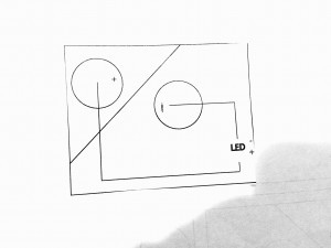
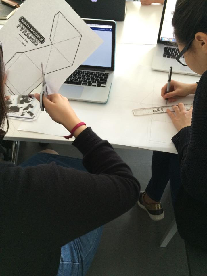
First, we started by creating the pyramid template to ultimately fold into the 3-dimensional pyramid shape. We researched different sizes and designs, but we decided on a simple, small three-dimensional pyramid template. We researched many different sizes online, and then copied one we found onto paper, measuring so the lines would all match up as you can see below:
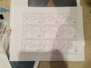
We also decided to print out an already created template, and use that as a practice pyramid to see what ours would look like in the end (you can see Sheena cutting that out in the first image). However, we created our own template from our research, and I traced it out in Illustrator, so someone could recreate it again with the vinyl cutter if they wanted to.
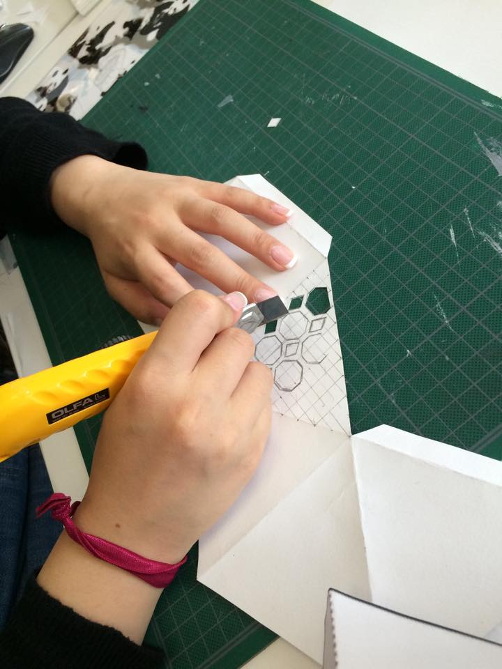
We cut out a geometric pattern to add a little flair to the simple pyramid, and here you can see Sheena cutting out the shapes:
And here is the Illustrator (screenshot) of the reproduce-able template I created in Illustrator with fold marks in purple:
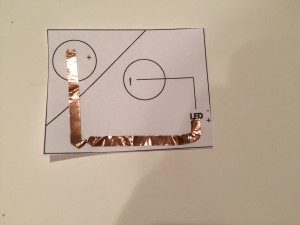
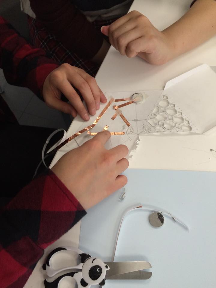
So, after we sketched out our pyramid design, we created the circuit pattern to connect the battery to light up our LED in the pyramid. We used copper tape in the interior of the pyramid, connecting the power source (battery) to the light (LED).
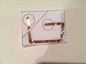
Here’s Sheena and Ice figuring out where everything should be placed:
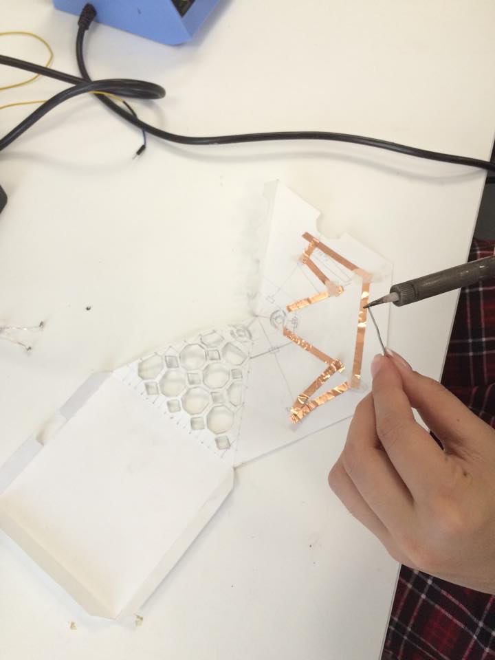
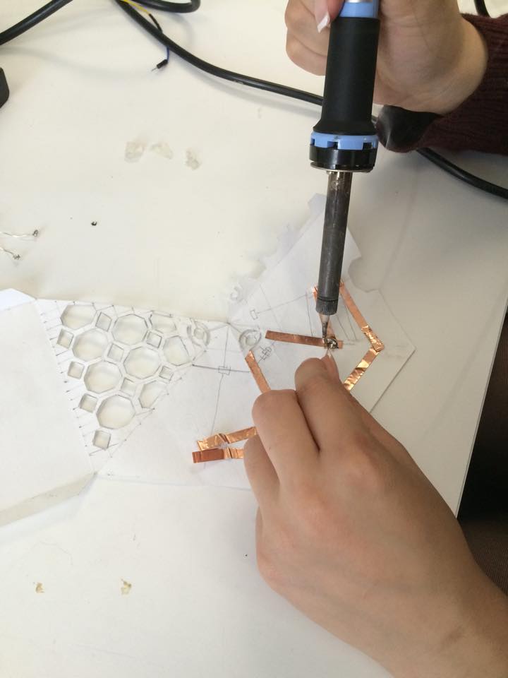
Once we figured out a successful design for the LED, we soldered:
So we soldered the LED and the battery onto the copper tape in order to complete the circuit. You can see this above and below Sheena is soldering the copper tape together to complete the circuit.
So, we soldered the copper tape together, and created a switch with the copper tape and the battery was then soldered on the left side (where there are two pieces of copper tape sticking up in the picture) and then the LED was attached where it says “LED”.
So in the end, after soldering and folding it back to the three-dimensional pyramid shape, this is the final pyramid (in the dark to emphasize the LED aspect):
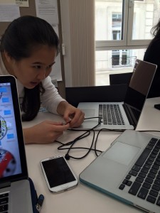
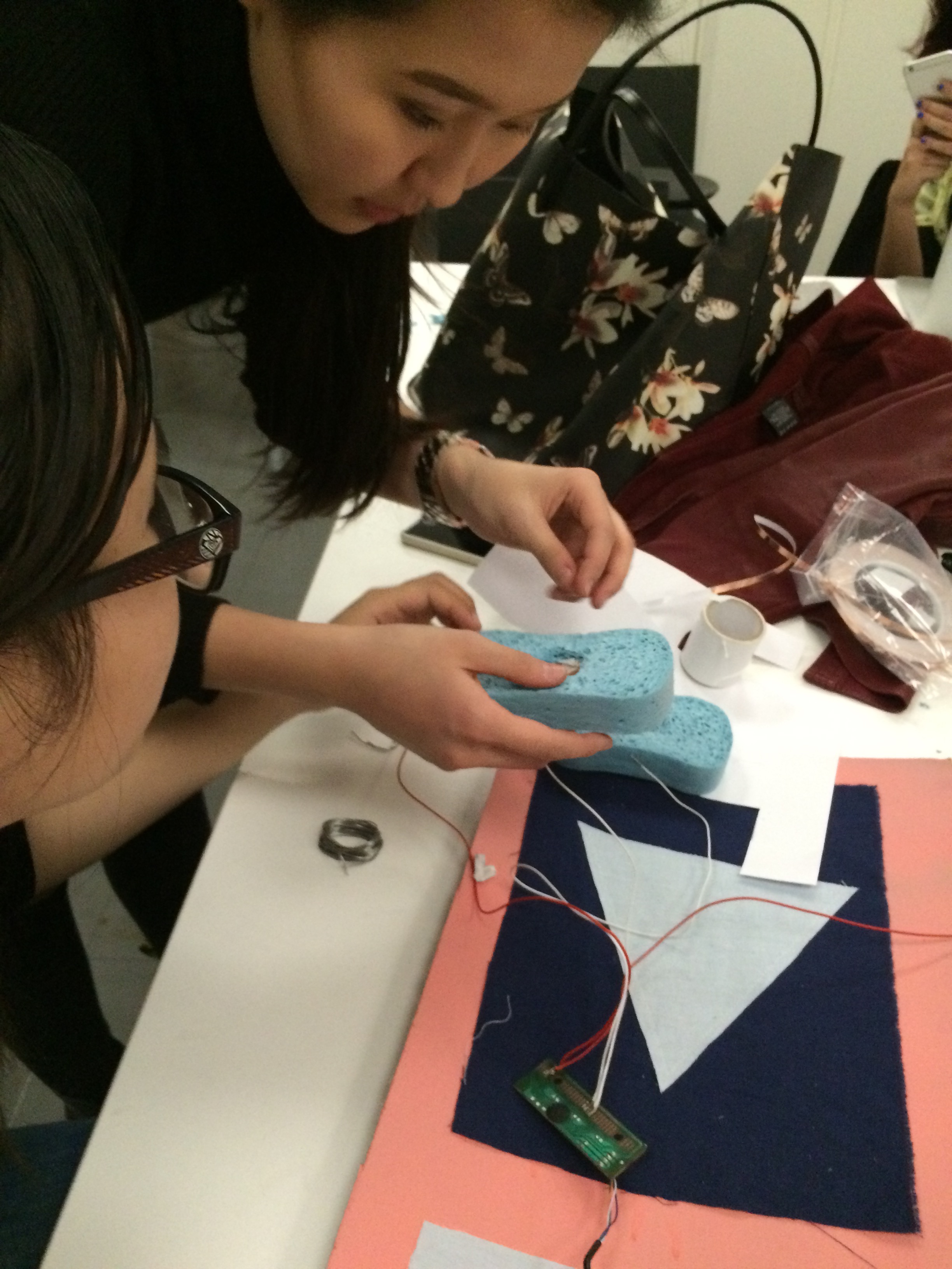
So this week, Sheena, Ice, and I (Lanie) hacked a keyboard (well, three technically, between all of us) and decided to create a party shuffle player for music. Essentially, one would tap the enter button to play the song, and then the shuffle button to play the next song.
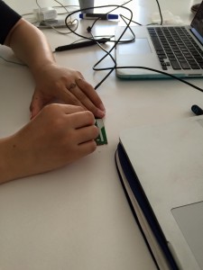
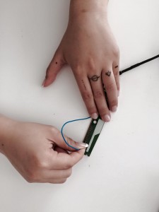
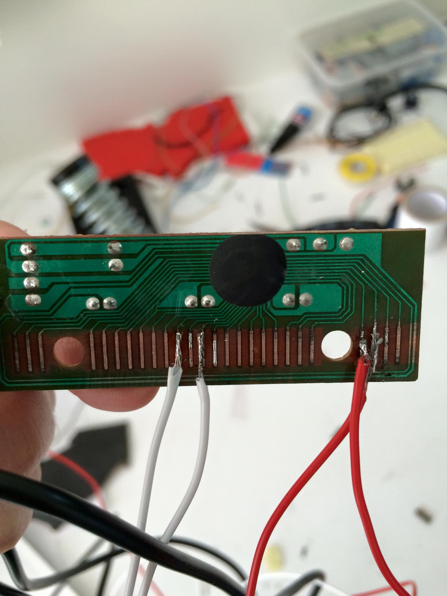
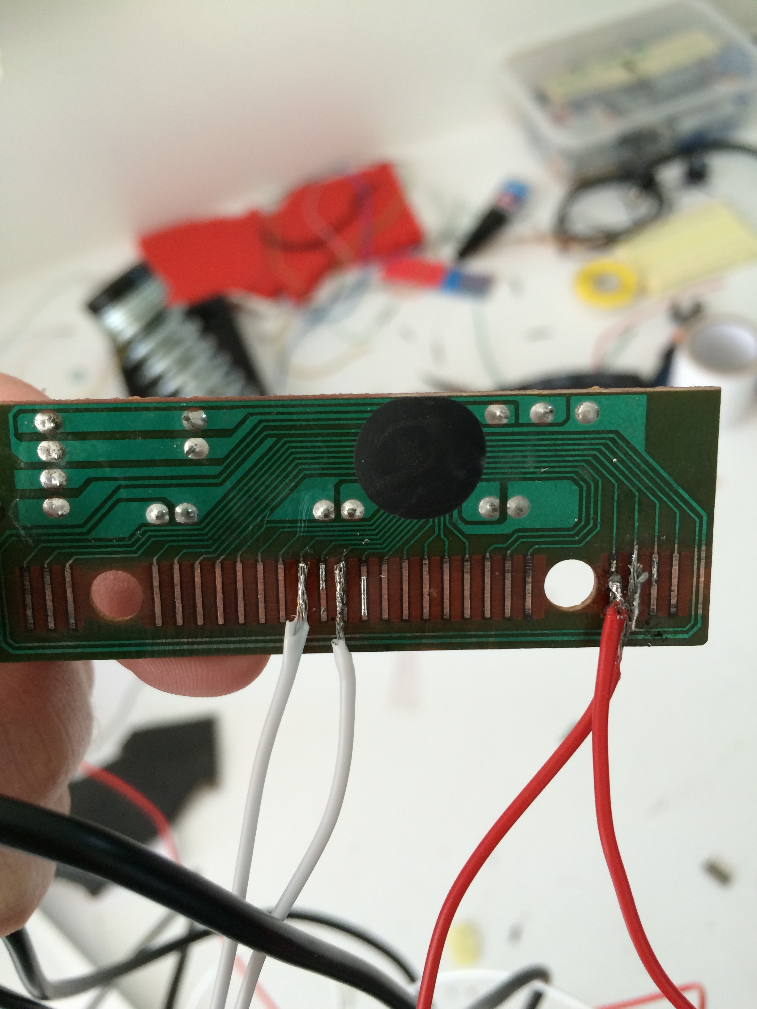
So first, we first took apart our keyboards, and then tested the wire on the board through trial and error, trying different combinations with wire. We tried so many, and it took very long, but eventually we did find what we wanted. We went through a few different projects-first we were going to do a video game, and use the up and down keys, but that seemed way too complicated, so we decided to do a music player. In the end, we went through three different circuit boards. We soldered every time, burnt many pins, but eventually, our third one was the most successful, with 3/4 pins soldered (one broke in the end, unfortunately-as of right now, but it may be fixed after this post has been uploaded so I will update accordingly if so). So, every time we had a new board, we had to find the keys that matched with the pins. It was definitely arduous, but we really just tried our best.
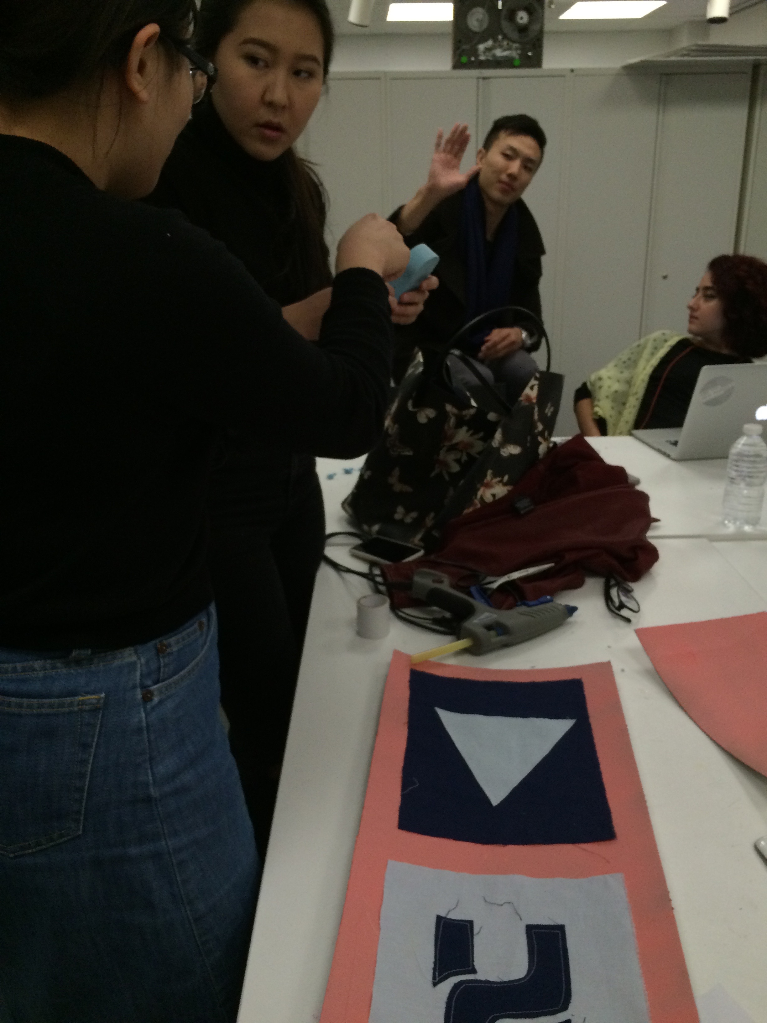
So for this music player, we used fabric, sponges, and the wire and circuit board. We created it so that when you press the sponges, you either play a song, or move onto the next one. We did this through finding the keys from the hacked keyboard. It’s a simple idea, but we put so much work into making it work successfully.
Here are the two fabric pieces that would be pressed to either play a song or play the next song.
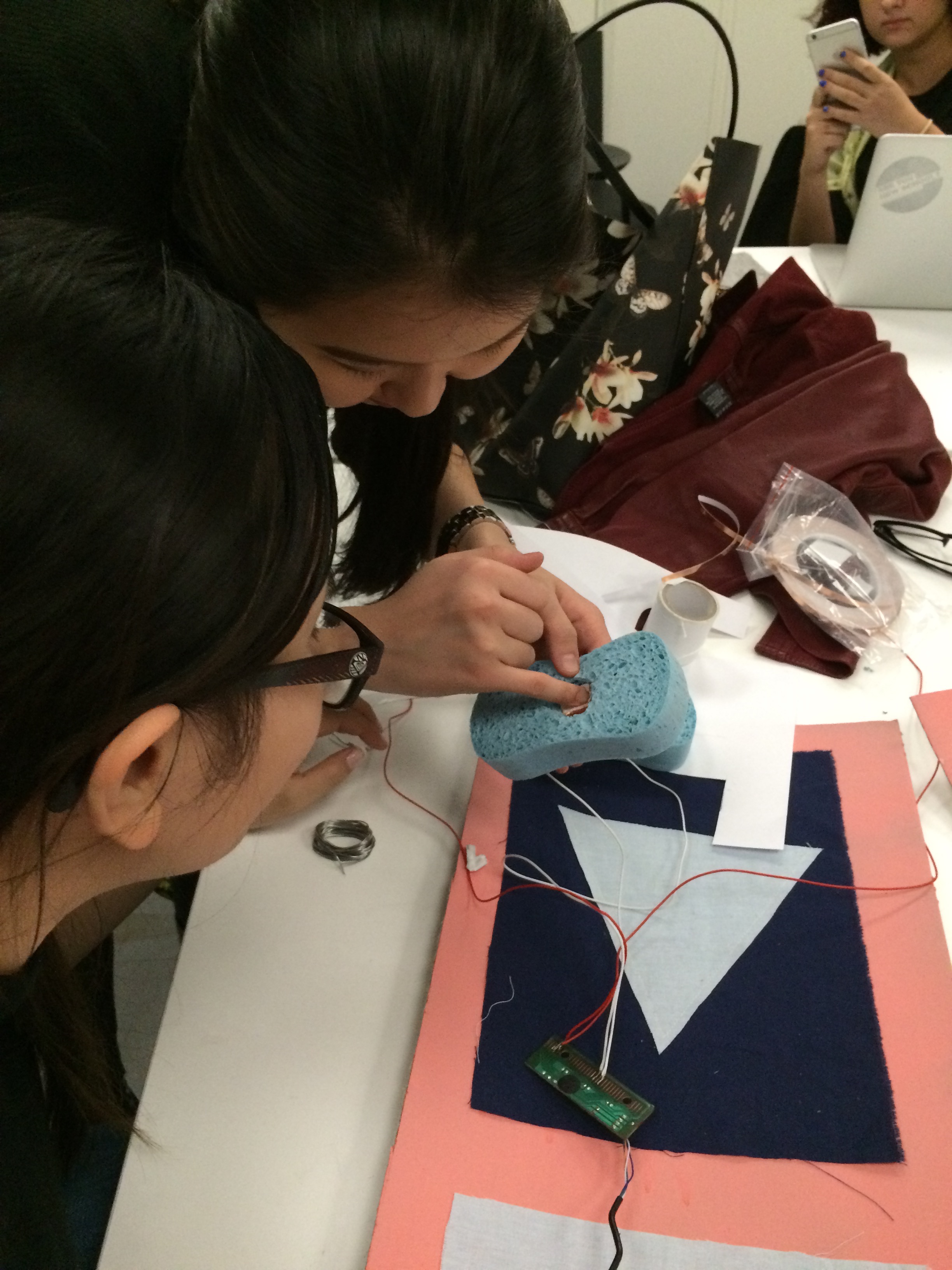
So, we sewed together the fabric, soldered the pieces together, and incorporated copper tape to stick the wires together to complete the circuit and allow for the board to work. In order for it to work the USB must be plugged into the computer, and when the sponge is pressed, the music is played or skipped, as previously mentioned.
Here is our process in images:
We first tested the pins to see what matched with what key:
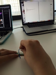
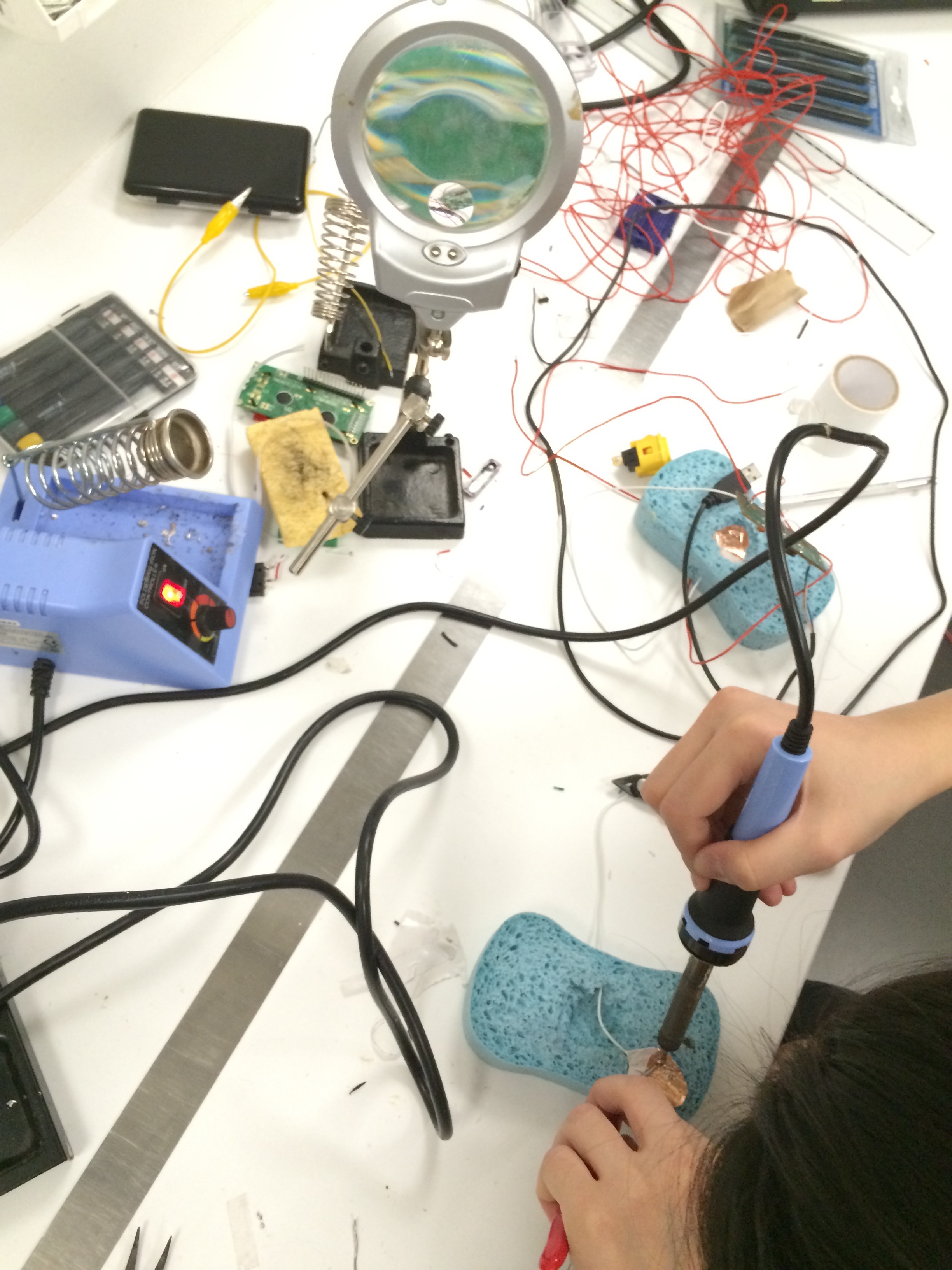
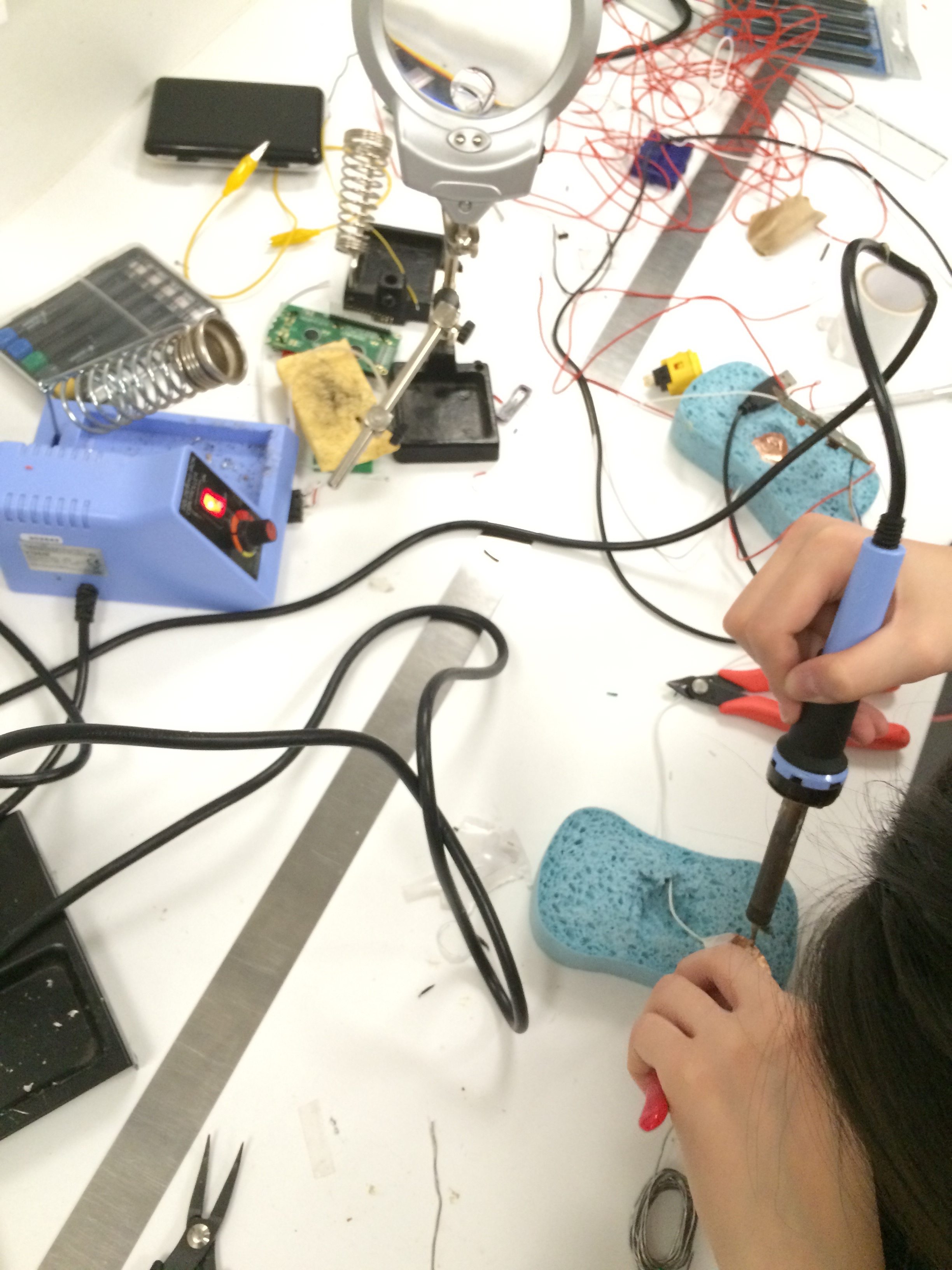
Once we figured out the pattern of keys, we started soldering:
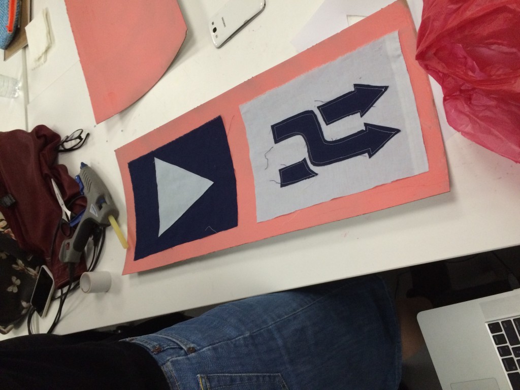
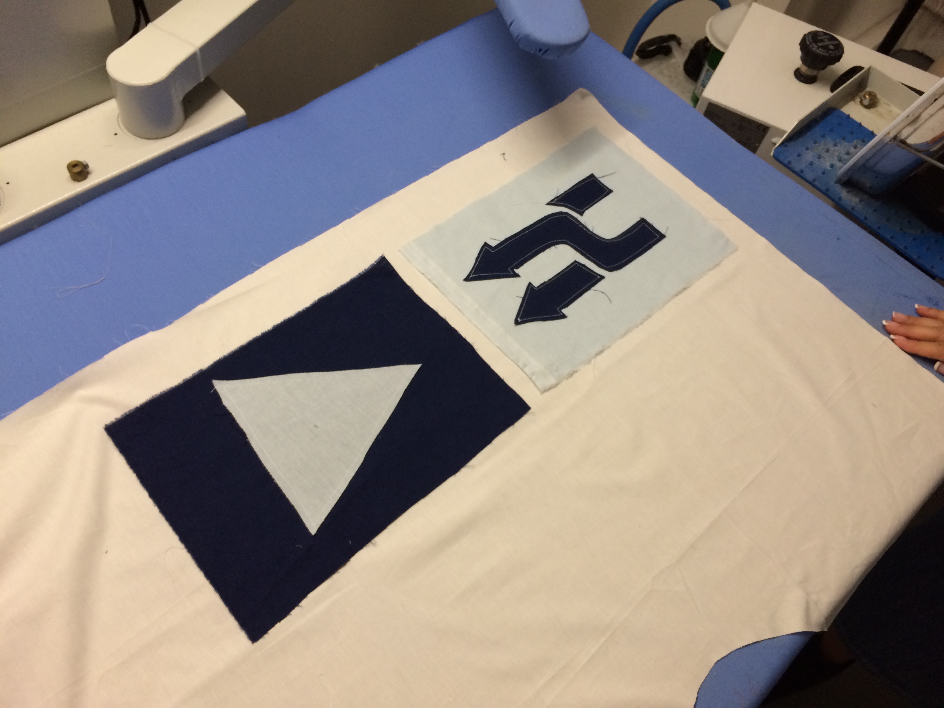
Then we designed our play and shuffle buttons we eventually sewed onto fabric:
Here is a video testing our sponges and circuit:
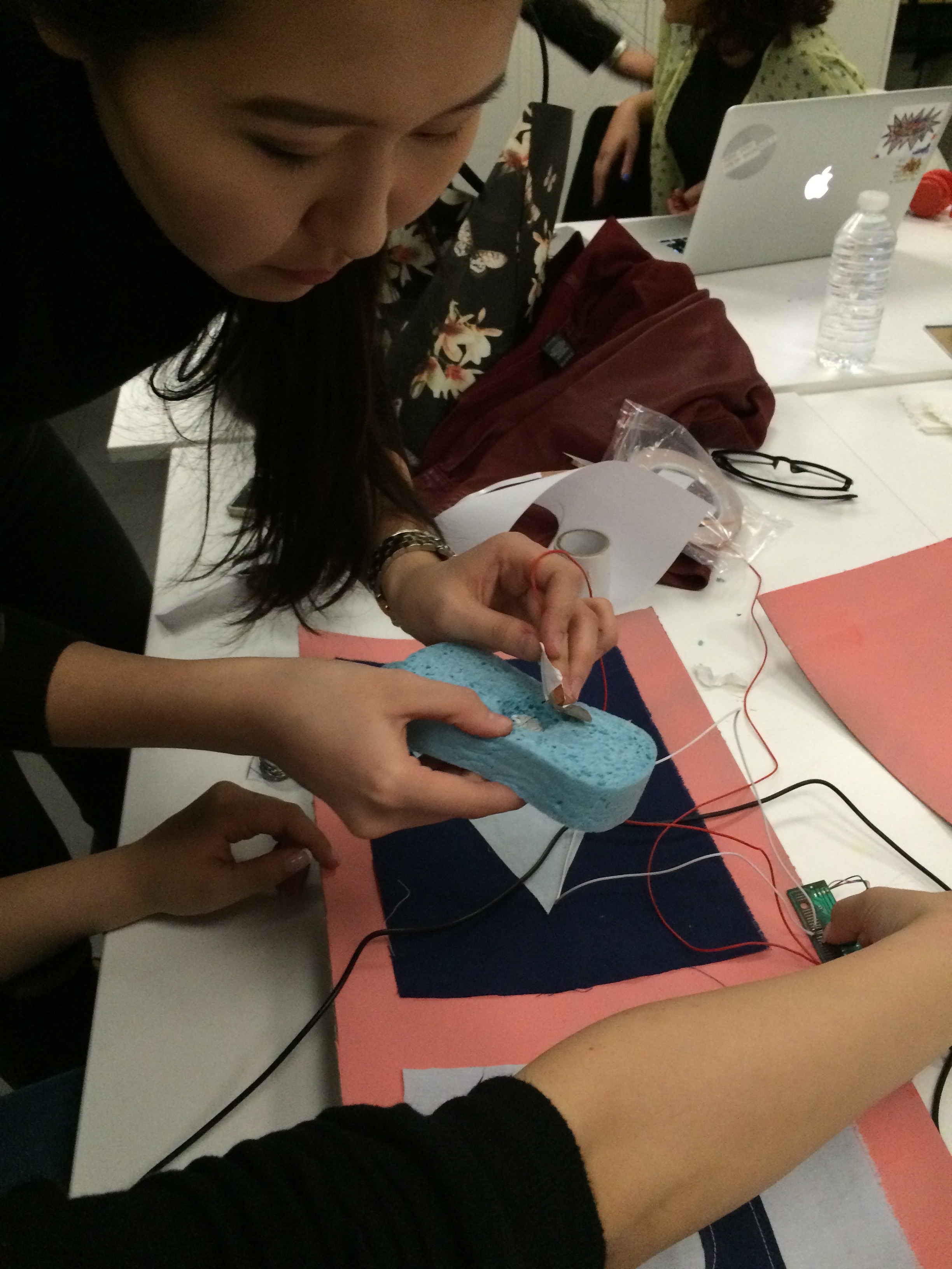
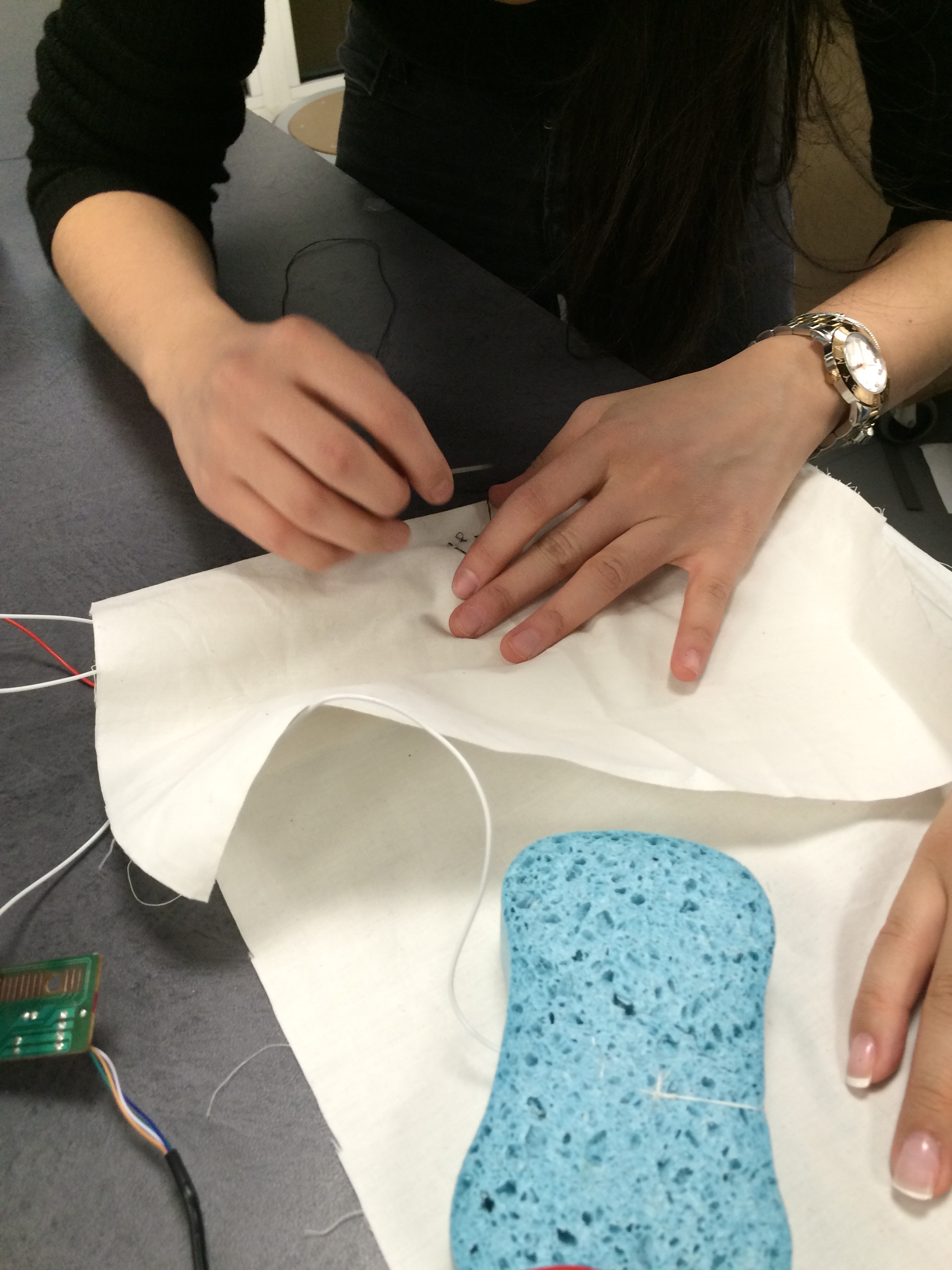
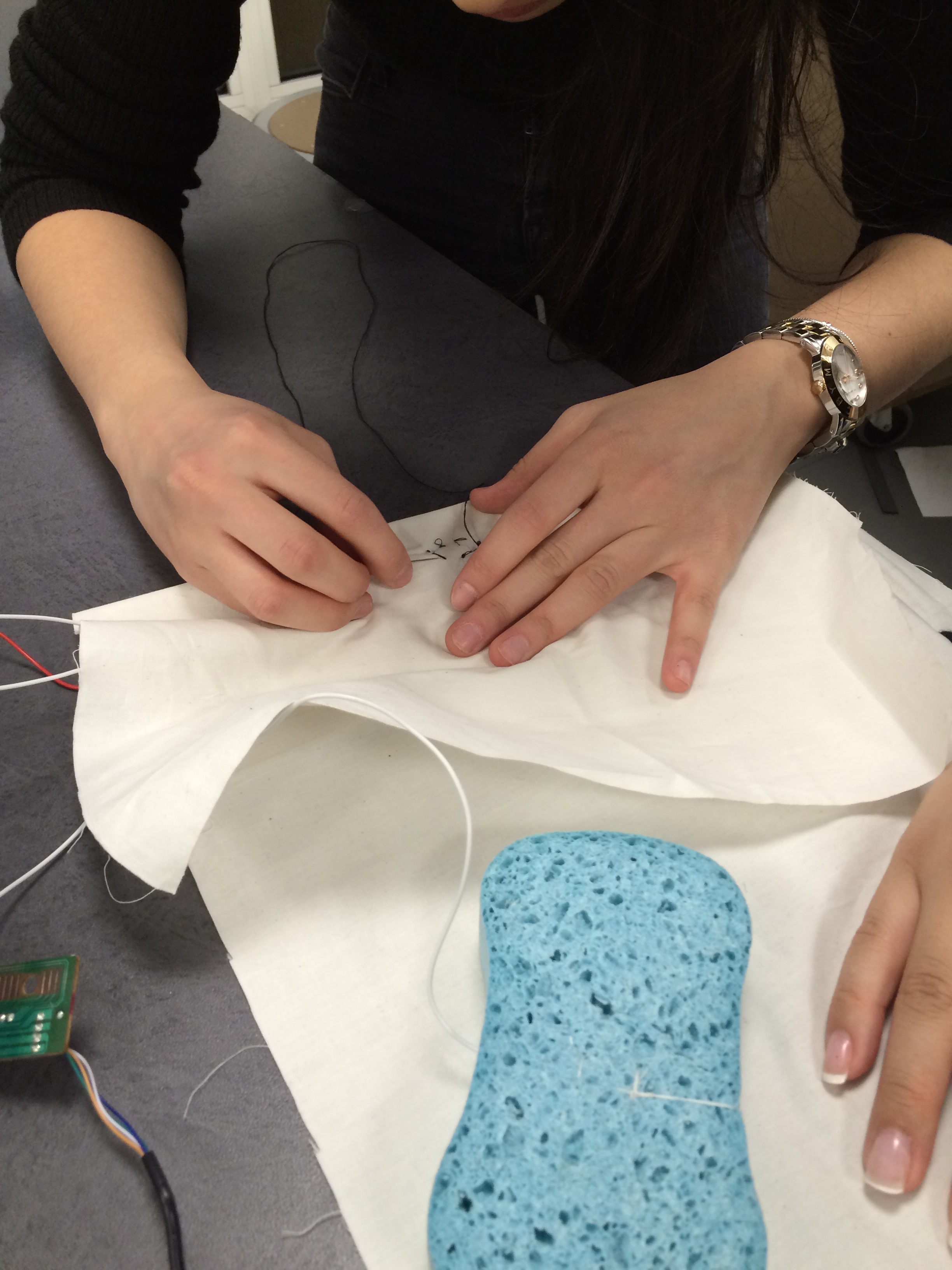
Then we figured out where the copper tape and wire would be connected to the sponges in order to complete the circuit:
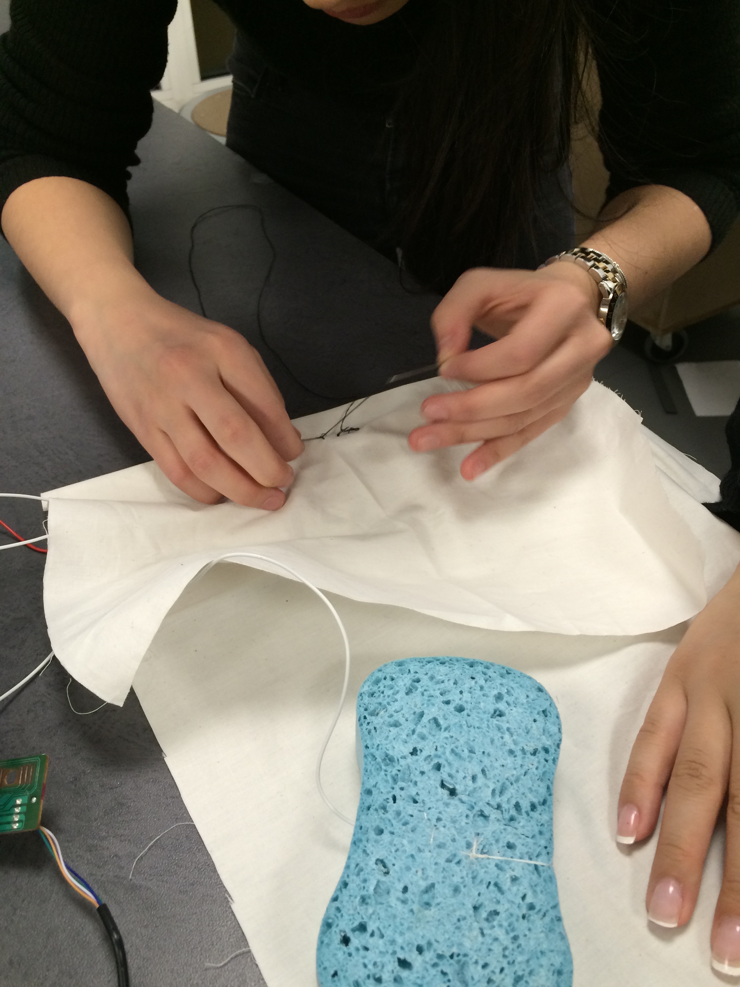
More soldering..this time we soldered the wires to the sponges/copper tape inserts:
Then we ironed the play button/shuffle pattern, sewed the copper tape and circuit wires into the fabric:
And did some more sewing of the copper tape component to complete the circuit:
This was the best video of our circuitry working before the solder broke off of our board:
So, we tried really hard overall to get this to work, and we learned so much from this project; soldering, circuitry, and most importantly, how to hack three different keyboards (in this case). It may not be as complete as we wanted, but we put an immense amount of work in, and tried our absolute best on this project.
So this past week, we worked on touch sensors made out of textiles. It was interesting to learn that you can create electronics from seemingly simple fabric, but the possibilities are endless with conductive fabric.
So for this project, I layered my fabric and sponges and sewed it all together (except for the main resistive piece in the middle because I was unsure where exactly to sew it, so I left it so I could move in the right position).
The first layer is nonconductive outside of two pieces of lycra, two pieces of foam, and then two pieces of (4 altogether) conductive silver fabric on top of the sponge, with the resistive piece of fabric right in the middle of it all, touching both sides of the conductive fabric.
Here’s what it looked like (I know my sewing skills could use some work, but it is all attached as I wanted):
So, that’s the touch sensor before I sewed it-I wanted to make sure it worked, so I did not sew it right away. So, when I checked it, it worked! So then I sewed all the pieces together.
So, this week we made garments with the textilo little board that we created ourselves. In order to create the textilo, we first laser cut a 5cm circular disc of neoprene. We first used the heat press to fuse together the glue paper with the conductive fabric, and then laser cut the textilo pattern out of the conductive fabric.
We then took off the pieces of conductive fabric that were not needed, and were left with the textilo pattern. It stuck onto the neoprene because we had previously fused the glue paper onto the back of the fabric. I also needed to re-iron the fabric onto the neoprene to make sure it stuck….
After securing the textilo fabric onto the neoprene, I soldered. OR at least attempted! Honestly, I struggle with soldering. I actually have experience with it from an engineering camp in middle school, but I had a hard time then, and I guess I still do.
My attempt at soldering all the components.
Anyway, I tried my best with this, and it turned out that some of the connections were broken on the board, or just not soldered as fully as they could have. I first tried to connect the broken connections with connective thread, but that still didn’t work!
You can see where I tried to connect the two with the connective thread above. But it did not work after I kept testing it (second picture)
More testing
So, Martin (thanks so much Martin!) helped me to solder the connections correctly. I also cut the wires on each component so they would be shorter, so they did not interfere with other connections. Even after this, however, my sensor did not work when we tested it. We tested it with the multimeter, with an official sensor, and we still got nothing. Eventually, we figured out that one of the alligator clips were broken! That just shows that sometimes things will go wrong, and you just have to keep investigating to figure out what the problem really is.
Using a sensor to test and see what was actually wrong
After Martin helped solder and correctly sewing the connective thread
So, after getting help and soldering my board, I figured out how I was going to position everything on my garment. I created a pocket to store the battery (which is huge, but I wanted to make sure I would have enough room). I originally wanted it to work so that when you press the pocket that would be on your stomach, it would make the speaker sound-like your stomach was rumbling. However, I had more issues than I thought, so I just had to make it simple, and the textilo and battery fit inside the pocket, but the sensor is on the outside of the pocket.
So, after sewing the pocket and finally figuring out what the problem was with my board and got the speaker to work, I soldered the speaker and battery wires to the board. I tried to sew them on, but I was extremely unsuccessful and just decided to try soldering. It seemed to all work, except when I tried to solder the positive red wire connected to the battery onto the textilo. The solder burnt the connection, and so I tried to solder it closer to the center of the board, but I think that is what created the short circuit.
My soldering of the battery and speaker…you can see the positive red wire is soldered in the wrong place (at least I think that is what caused my issue).
Close up view
However, I still kept pushing forward, and sewed my garment together to create a full project. I sewed my sensor on with connective thread, and the textilo board onto the shirt above the pocket. In the end, the short circuit made the 555 component heat up, so I had to unplug the battery. Though it may not work now, I do understand how it would work and I have a video of it when it all worked:
And here is the shirt after everything was sewed on:
I used connective thread to connect the sensor to the board, but there was a short circuit, so it did not correctly work in the end. It made sound, but not in the way I wanted it to. I did get it to work at one time, and I learned a lot so I will definitely work on my soldering skills in the future.
For my final project, I first thought I would be creating a three dimensional wall art piece incorporating simple LED lights as well as different types of LEDs; a light sensor, a microphone sensor for detecting sound, and a timer circuit. I actually did create the main elements out of paper, and also utilized copper tape and coin cell batteries to create successful connections to the LEDs, but my final idea was a little different from my original.
I found inspiration through Jie Qi’s art works that incorporate paper and electronics, for example this pop-up book shown to me by Martin (thanks, Martin!):
And the living wall made in the MIT media lab:
Here is my original idea:
These pictures are unfortunately not of the best quality, but the project on the right by artist Janice Caswell is serving as inspiration for my project. I will (and did) use paper, and other materials if it seems appropriate, to create my installation incorporating LEDs. I thought I would loosely create a web representing connections. This project is very individual, so it can be customized, but for the tutorial, I will be clearly explaining how to create the basis of a project like this. It is easily customizable.
I will keep updating on my process once I really get going-but right now I am waiting for my components to come in the mail-which will be very soon! It will be easier to map out exactly what I am doing once I have everything in front of me.
Update as of December 13, 2015-
So I tested the process of the string abstract technique, and I realized that since I will be utilizing copper tape to connect my LEDs. the technical aspect will not be hidden by my installation as the strings are too thin. So, I have decided to instead create a wall garland that will be easier for anyone to reproduce, and create on their own. It will feature shapes (right now I deciding on whether I should do triangles or circles) illuminated by the LED, which will be in between to sheets of paper. I will have designs on each lit-up shape, and right now I am thinking of constellations or images of the night sky.
I was really inspired by these garlands: http://miavril.bigcartel.com/products produced by Virginie Sannier-Dorémieux who is actually from Toulouse, France! I will not be sewing the garlands, but simply attaching fishing line or string between the shapes. I have already designed and engineered how it will all work, and now I just have to put it all together.
Here is how my final project all came together:
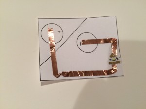
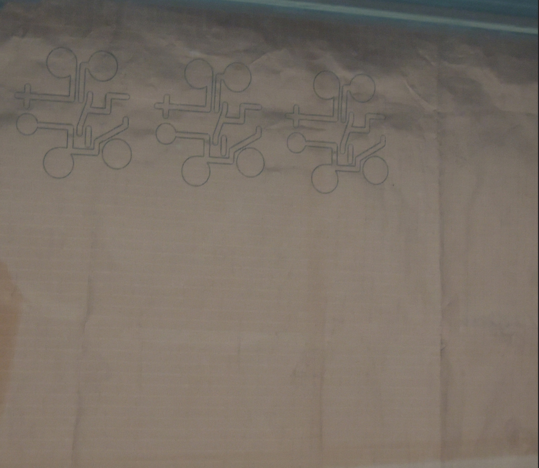
Originally, was struggling to come up with an idea to use with my LEDs. I knew I wanted to make something with lights, but I was not sure what. So, after researching more projects and seeing Jie Qi’s work with paper circuits and circuit stickers:(http://technolojie.com/circuit-stickers/), I was inspired, so that’s how I came up with the idea of a paper star light-up LED garland. In order to make this, I ordered online LED stickers, 3 volt coin cell batteries, and copper tape. As soon as all my components came, I started to experiment, and made different connections, like this one:
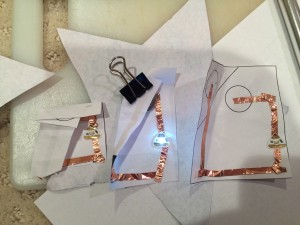
but I realized I did not know what I was going to make with this parallel circuit, and I knew I had to go simpler if I wanted to make something successful. So, I decided on the simple paper circuit LED. I created my own template that would fit inside my stars:
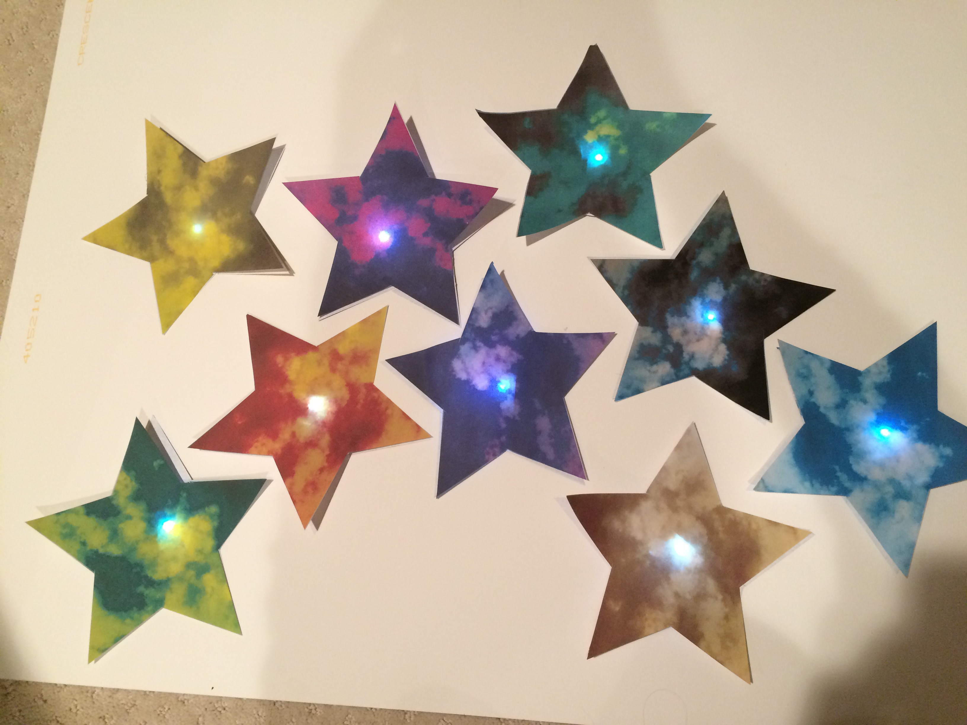
and used it inside all 10 of the paper lights I created. After getting the right size to fit inside the star shape, I developed my LEDs.
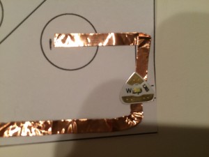
Placing the copper tape to create the correct connections, and then adding the LED sticker and battery:
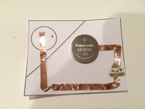
And then, I tested the connection by pressing on the battery, and most of the time, the circuit worked well. Some of the time, I realized I folded the copper tape too much or not as well as I could have, so the connection was weak. Then I just re-made the circuit, and learned from my mistake.
And then, after testing, I taped the battery into the circuit. Of course, soldering would have been the best way to affix the battery to the copper tape, but I do not have a soldering iron. Actually, at first, I was going to use a glue gun to glue the battery to the copper tape. But after researching this, I quickly learned that because the glue is hot, it weakens the connection and is a horrible way to connect circuits! So, I decided on tape. I made sure it did not touch the copper tape as the strongest tape I found turned out to be silver. Like I said before, I would have preferred to solder, but this was the only option for me as I am working from home. However, the tape worked extremely well and provides an excellent way to keep the battery in the circuit.
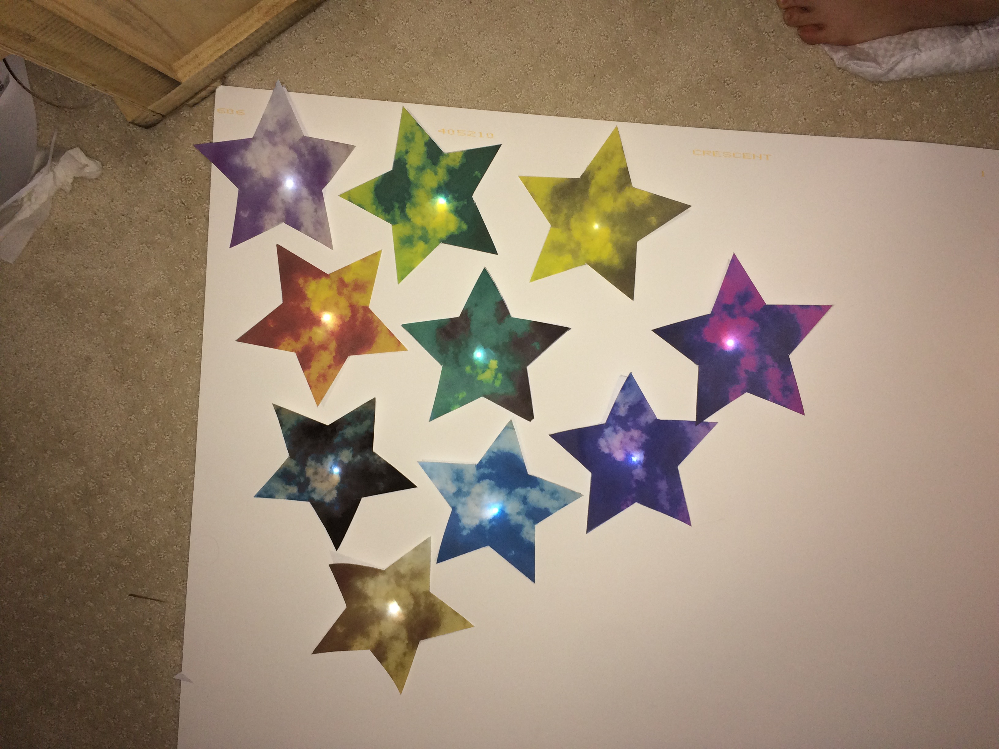
So I decided to make 10 stars, so I had to make 10 paper circuits. I ended up with around 14 because some were having issues, or stopped working. And before I even came up with the official circuit, I had many prototypes:
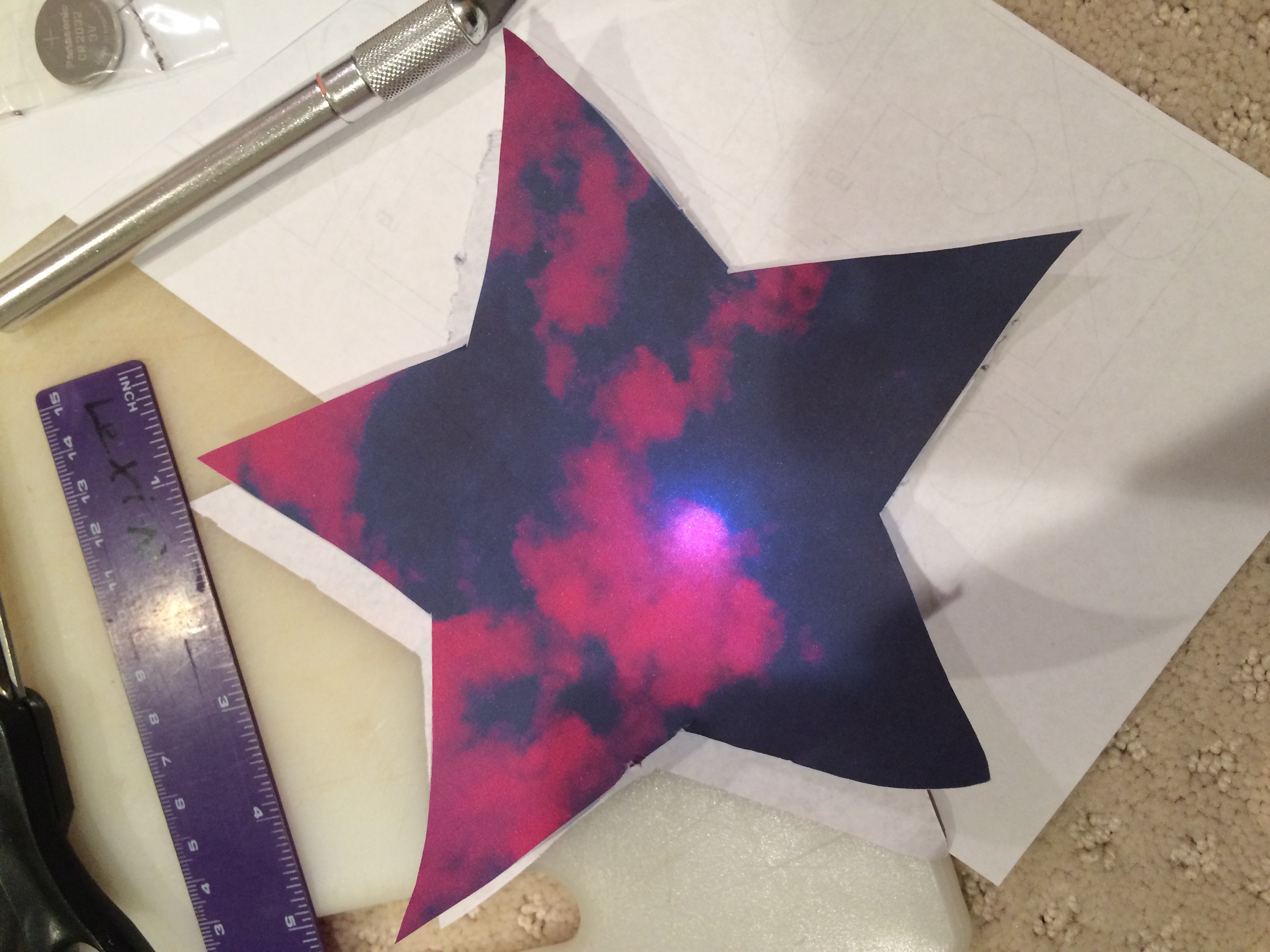
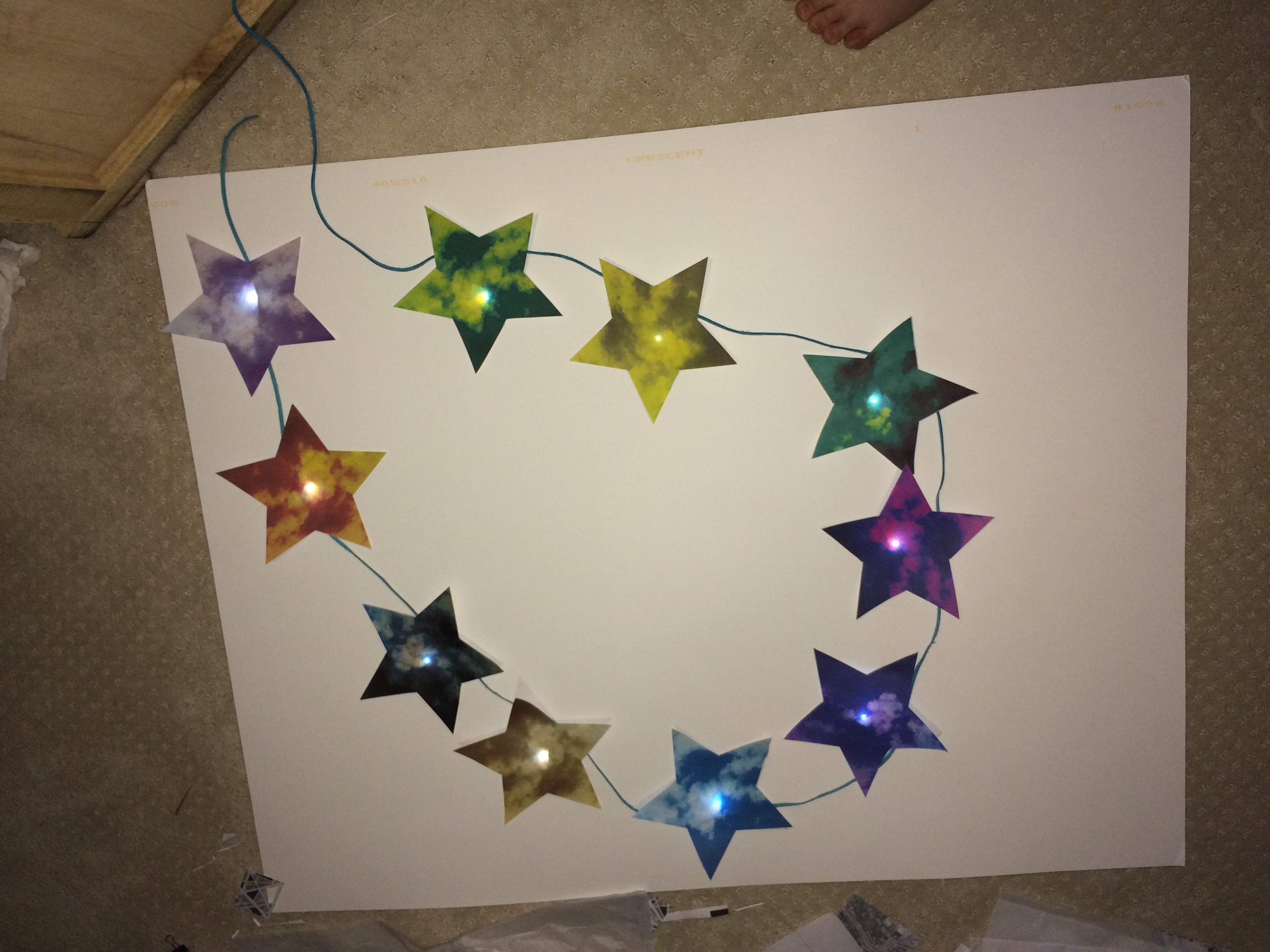
Next, after I tested and decided on an appropriate circuit for my stars, I printed out my multicolored stars and taped the circuit to them, using double-sided tape. I designed the stars myself, using my own photograph of clouds and remixing it with different colors, so each star is a different shade.
Here are the 10 stars I created in Illustrator :
I thought that printing on card stock, or thicker paper, would be a great idea because then the stars would be very durable, but once I experimented with the thicker paper on top of the LED, I learned that the LED was not visible because the paper was so thick. So, I used plain printer paper, which is super thin, but allowed the light to shine through.
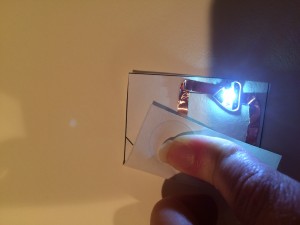
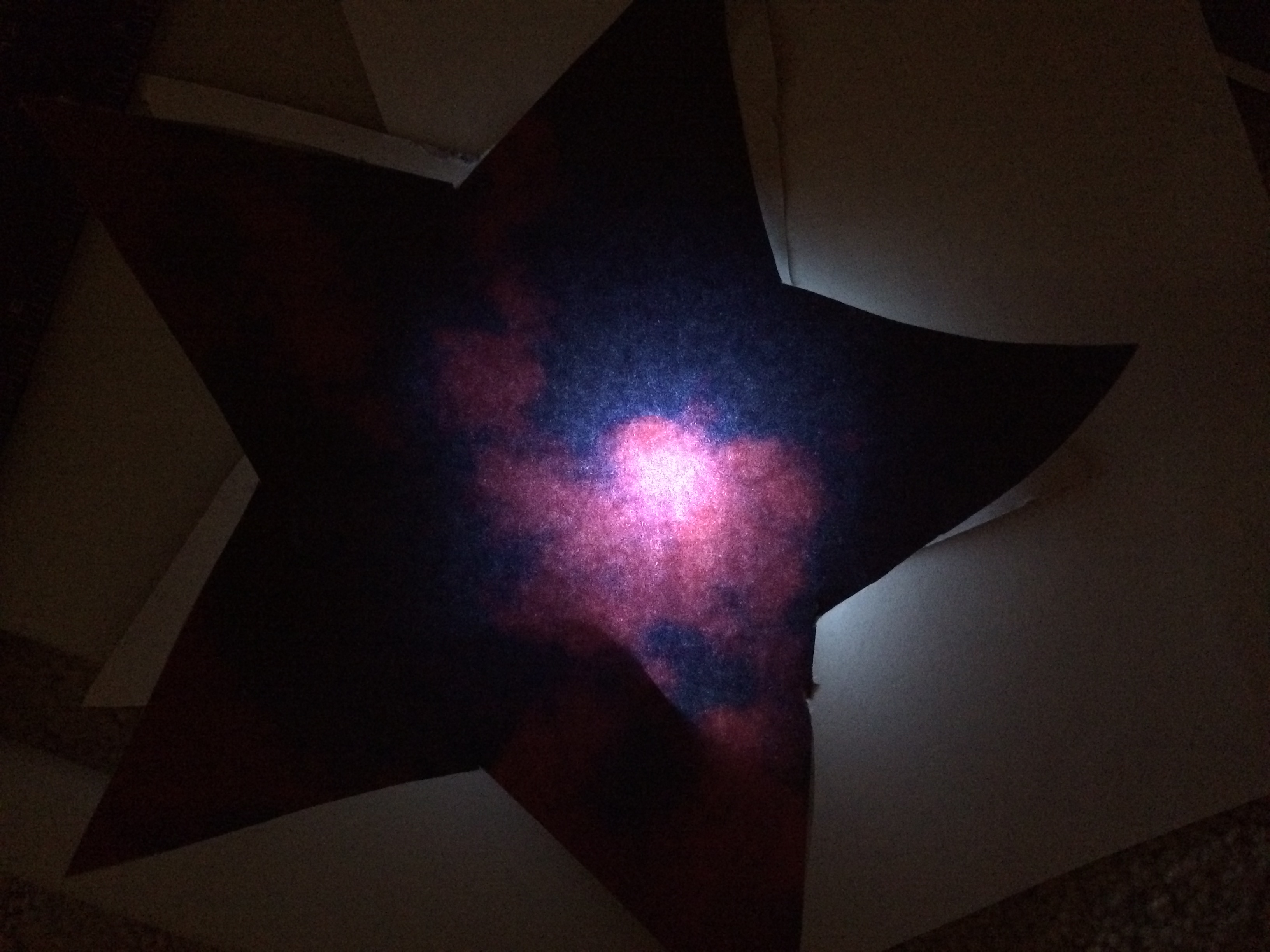
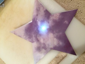
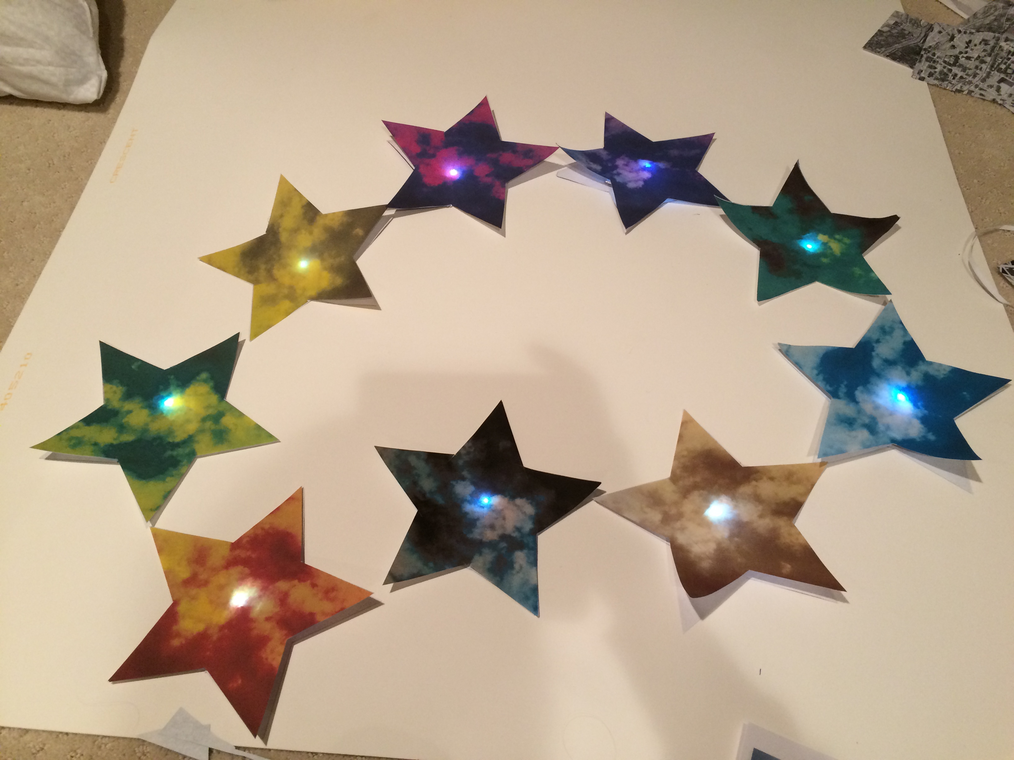
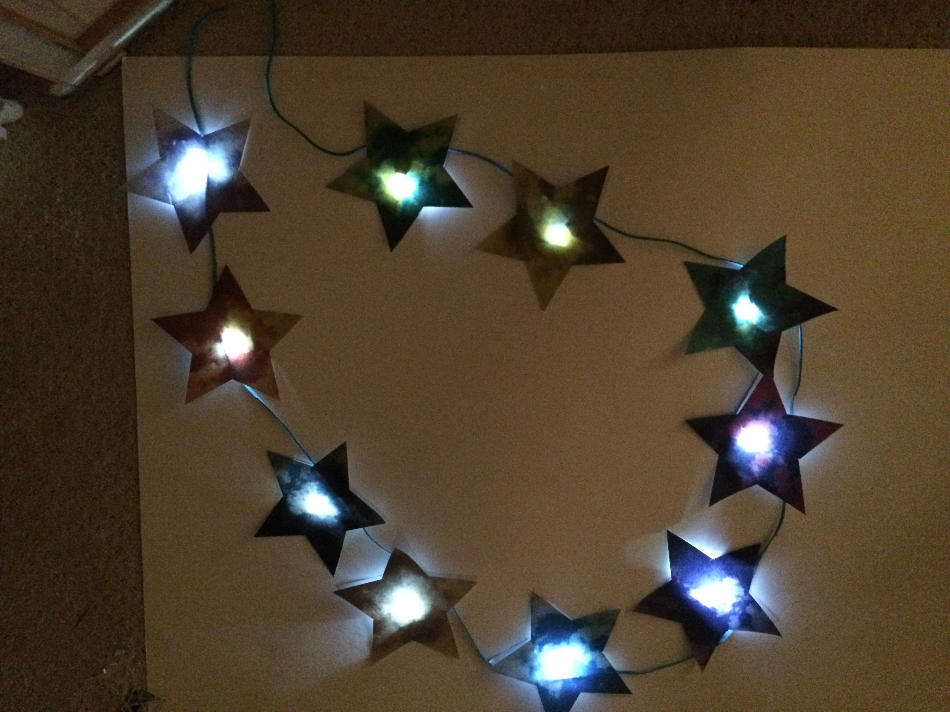
After I taped all the paper circuits to the stars, this is what they looked like:
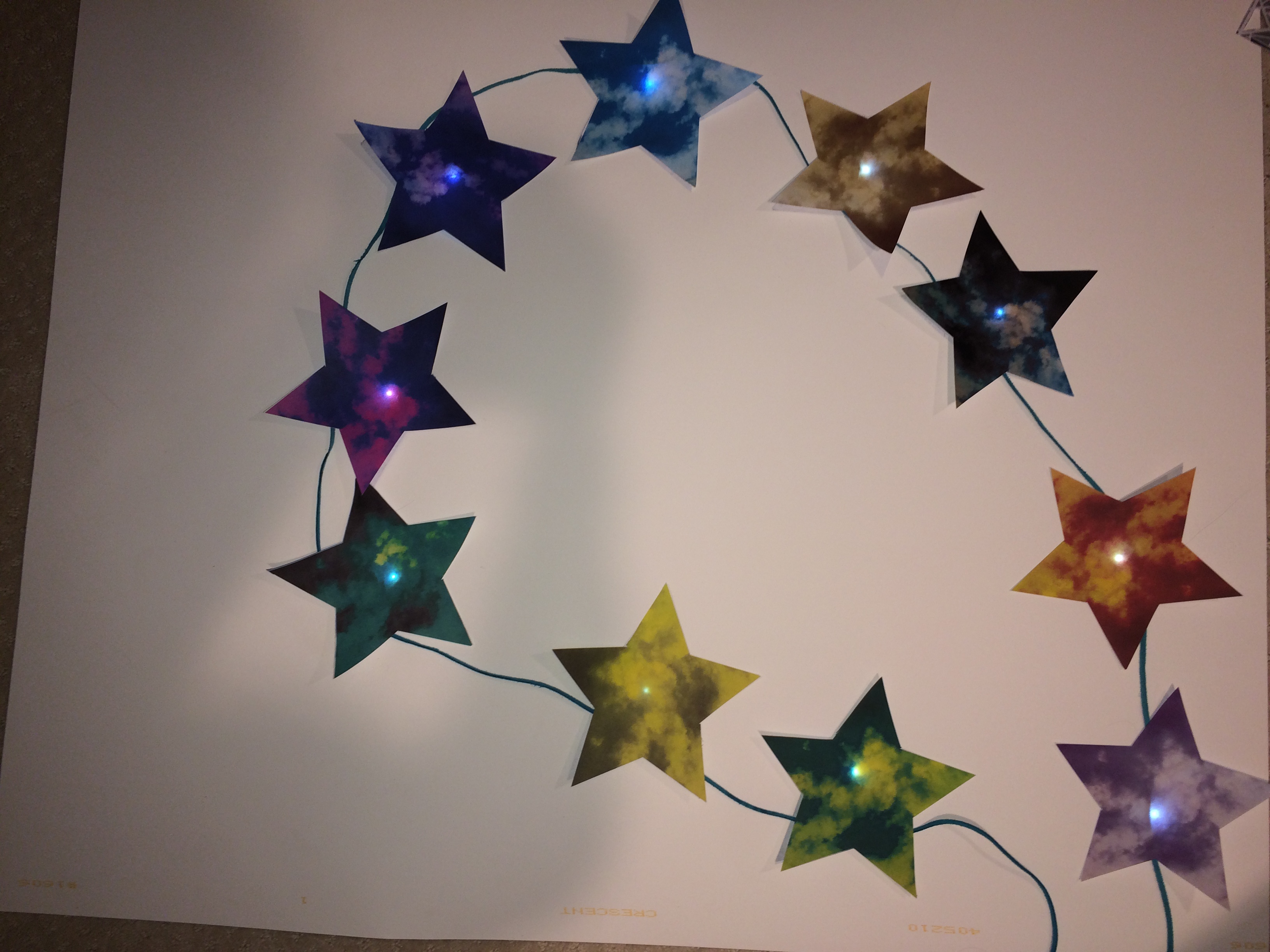
After looking at my stars all lit up and successfully working, I started creating the garland. I tried a blue suede thread just for a test:
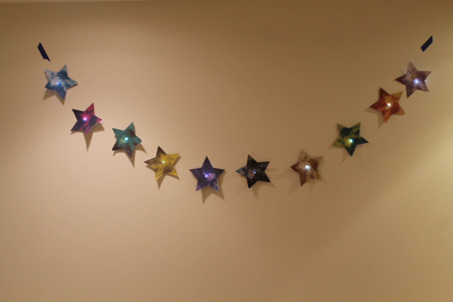
But, ultimately, the best choice in hanging material was clear fishing line, so the stars appeared to be floating:
I had to tape the garland on the wall using painter’s tape, which is blue, because I did not have any other method that wouldn’t take the paint off the walls of my house.
After I took final photos of the garland, I discovered that when I took pictures of it in the dark, they blurred and created a real beautiful light painting effect. So, if anyone decides to make this in the future, it is not just a pretty light fixture to make, but the LEDs also allow for very successful light painting via long exposure photography. You just have to take photographs with a long exposure, and the results are pretty awesome and unexpected because the LEDs actually leave bright, multicolored trails.
One example of the light painting (and more in video down below):
Overall, the development of this project took a long time, and I really was struggling to figure out a really successful project, but I feel like I accomplished something really well-made. I am proud of it and hoping maybe someone will make it themselves!
And here’s a link to a video documenting my project and the light painting images I created:
I couldn’t do this project without the inspiration of Ji Qie, the help of Martin Debie, and the most helpful websites: digikey.com, chibitronics.com, http://miavril.bigcartel.com/products, and http://technolojie.com/circuit-stickers.
For the flip flop project, I decided to create a generative design in Processing, utilize a sensor with the lilypad, and then ultimately produce a puzzle-with a piece for each of my classmates-out of my design.
So, I first found a code for a generative pattern to be created. I found a very simple one that just created rectangles and circles, and so when you pressed on the sensor, a rectangle is created, and more are produced depending on how hard you press on the sensor. Also, when you move the mouse, circles are created, just adding another element to the design.
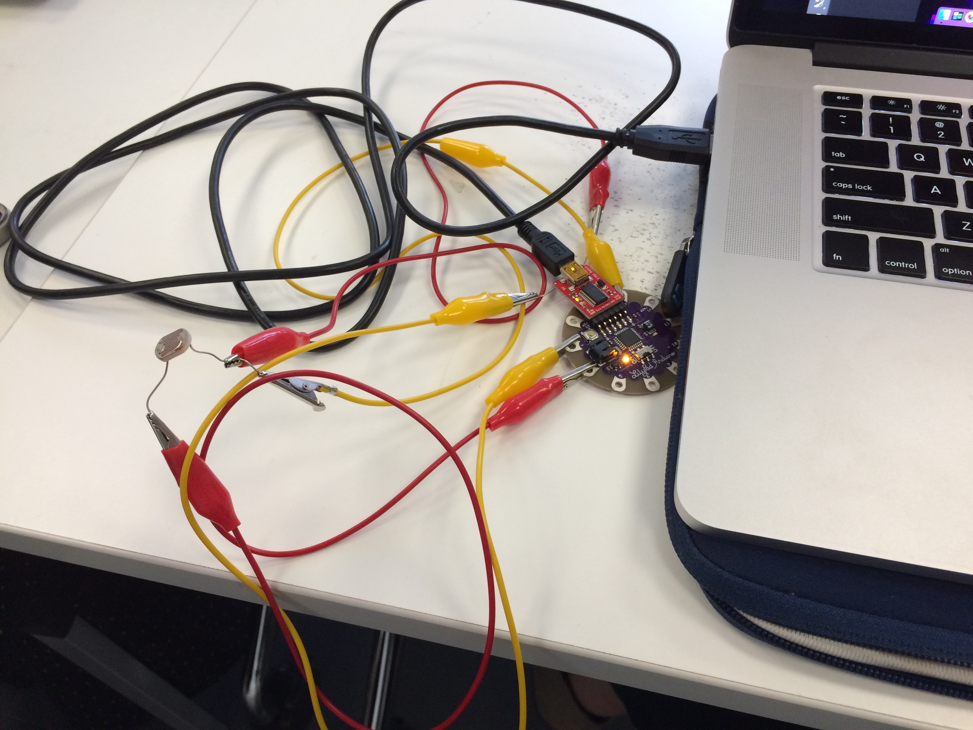
Here is the Lilypad and sensor I used:
Here is a video of the sensor to Processing process:
void draw() {
// Call the variableEllipse() method and send it the
// parameters for the current mouse position
// and the previous mouse position
value=arduino.analogRead(3);
variableEllipse(mouseX, mouseY, pmouseX, pmouseY);
fill(random(0,800), random(0,30), random(0,500),value/4);
rect(value/4,mouseX,200,20);
}
// The simple method variableEllipse() was created specifically
// for this program. It calculates the speed of the mouse
// and draws a small ellipse if the mouse is moving slowly
// and draws a large ellipse if the mouse is moving quickly
void variableEllipse(int x, int y, int px, int py) {
float speed = abs(x-px) + abs(y-py);
ellipse(x, y, speed, speed);
}
and this:
import cc.arduino.*;
import org.firmata.*;
// setup – runs one time
void setup()
{
// set a stage size of 500 x 500 pixels
size (500,500);
// smooth all drawing
smooth();
// don’t draw an outline around your shapes
noStroke();
// draw all ellipses from their center point
ellipseMode(CENTER);
}
// draw – runs once a frame
void draw()
{
// fill all shapes with a solid black color with a very low opacity
fill(0,0,0,10);
// draw a rectangle that fills the whole screen
// don’t draw this rectangle if you don’t want to erase the screen each time
rect(0,0,width,height);
// fill all shapes with a white color from this point forward
fill(255);
// draw a small ellipse (20×20) where the mouse is
ellipse(mouseX, mouseY, 20, 20);
}
So, once I came up with a sketch that I thought looked aesthetically pleasing, I took a screenshot, cropped it, and put it into Illustrator to create a puzzle. It is a tangram-type puzzle, and here is what the final looked like:
I then wanted to laser cut each of the 12 pieces so everyone could have one, but I left Paris before I could, so I am extremely grateful to Ivan and Martin who laser cut it for me. I don’t have the images (yet), but I am sure the laser cut pieces look great!


 (http://technolojie.com/circuit-stickers/), I was inspired, so that’s how I came up with the idea of a paper star light-up LED garland. In order to make this, I ordered online LED stickers, 3 volt coin cell batteries, and copper tape. As soon as all my components came, I started to experiment, and made different connections, like this one: