In this session, we will create a project around the concept of Flip-Flop, which is explain in the following presentation.
To make it we will use processing software:
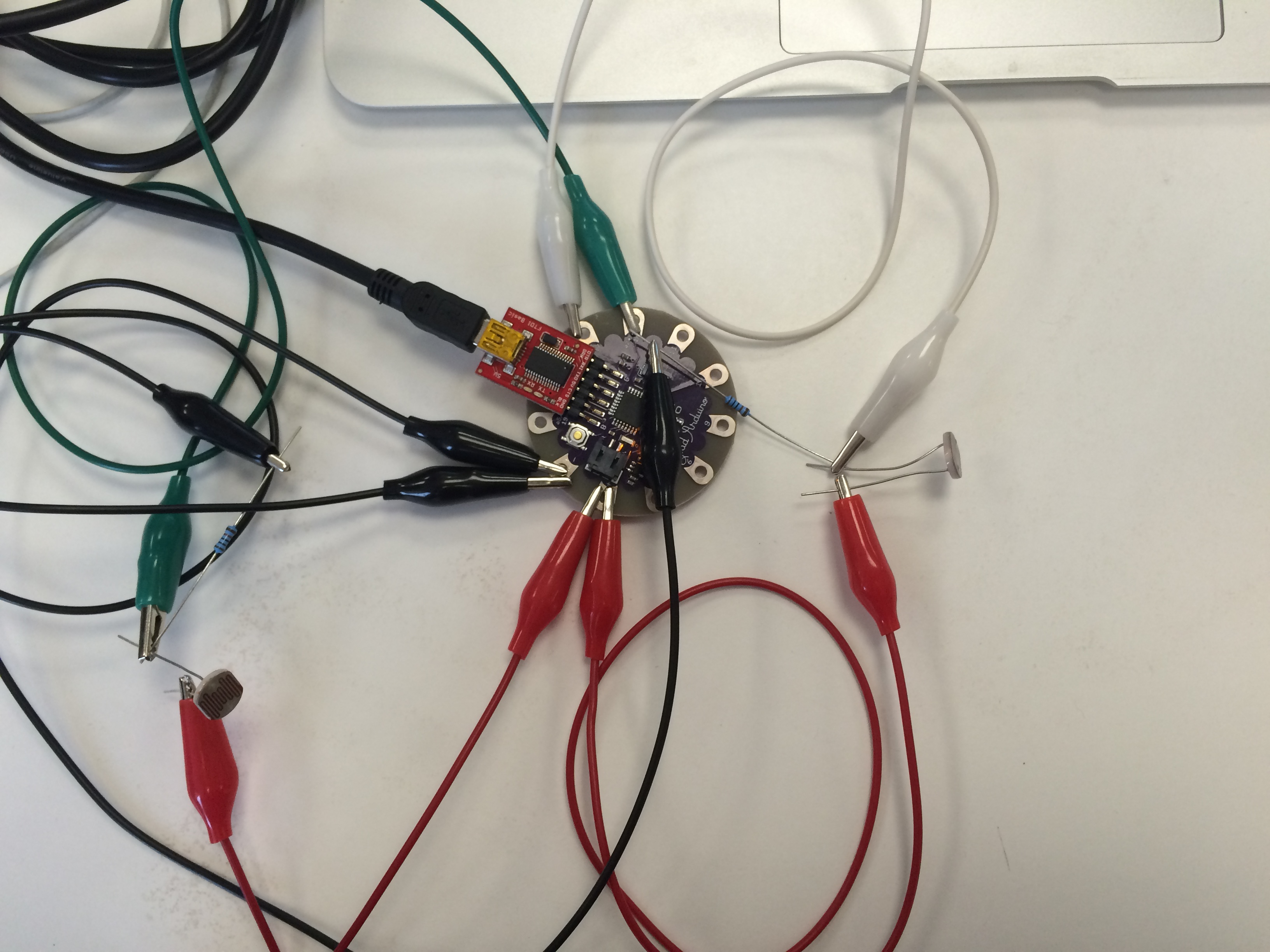
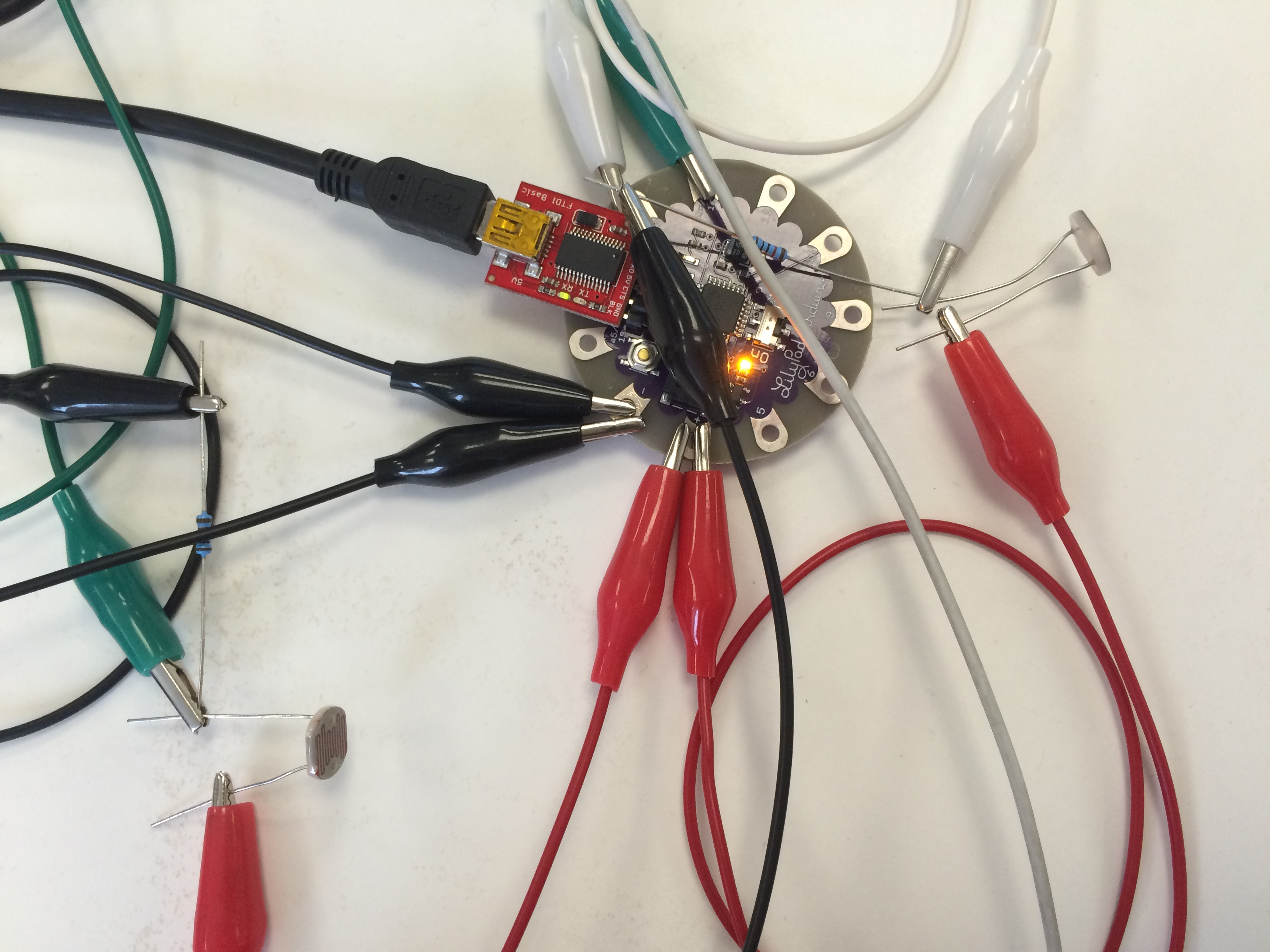
We are going to use to option to connect processing to your lilypad arduino and create connection between physical and digital world, serial communication and firmata+
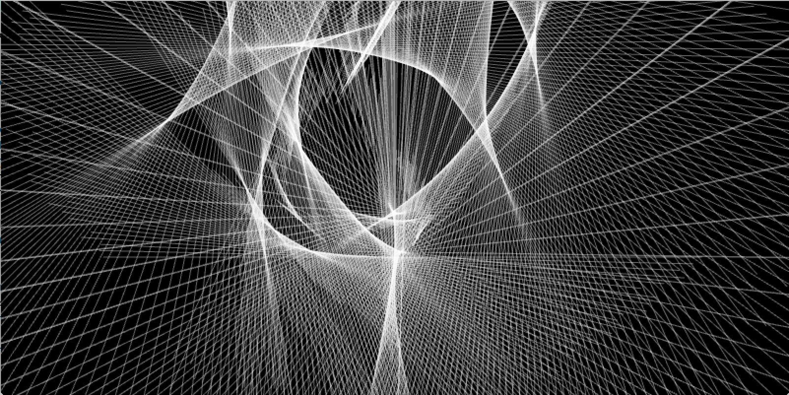
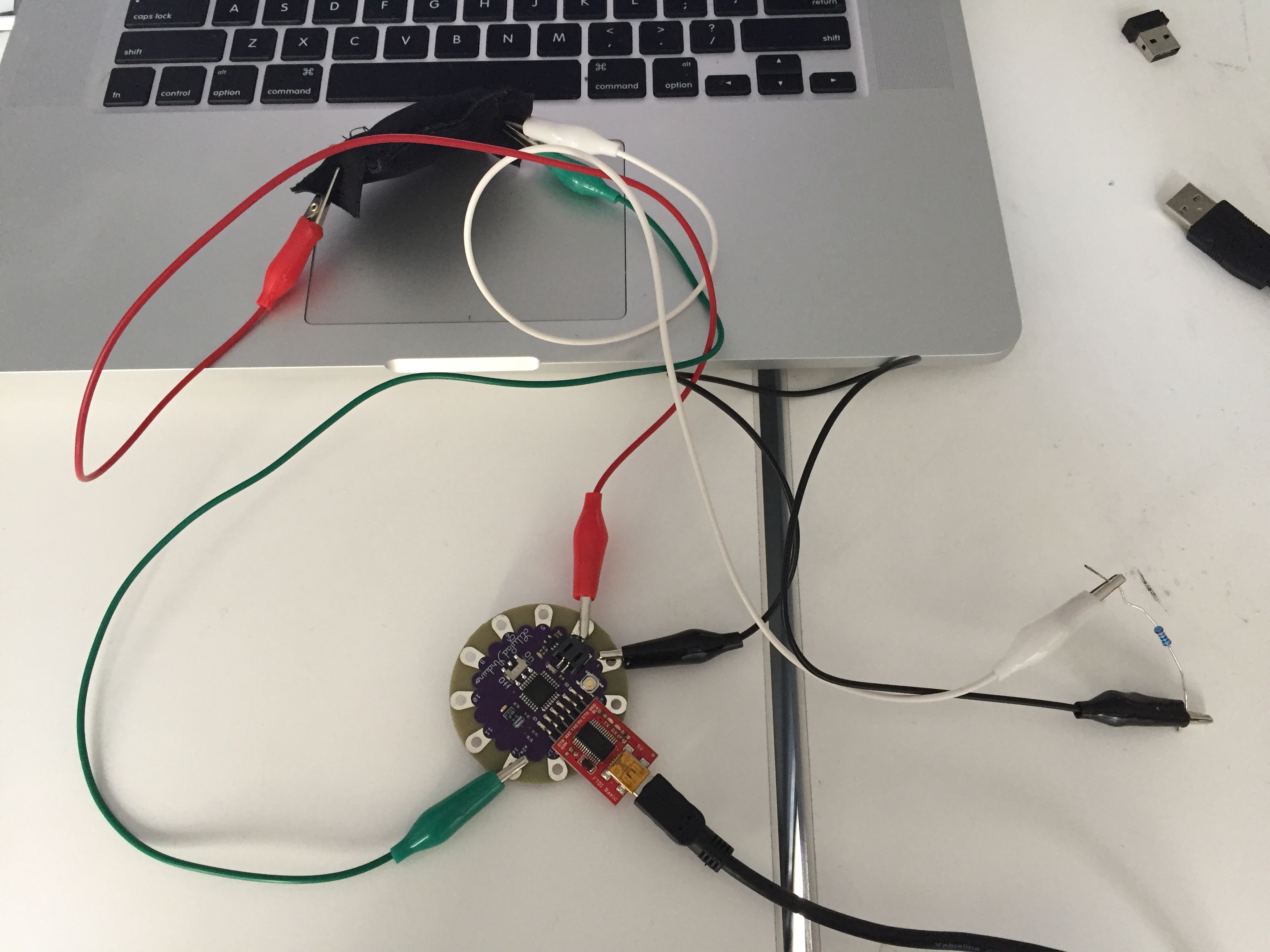
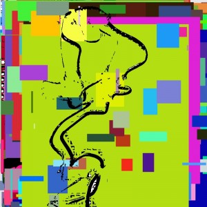
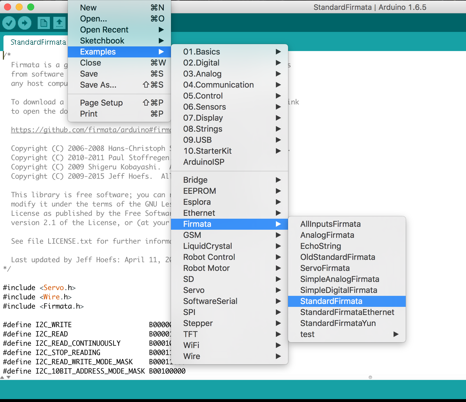
For this assignment, I wanted to create a generative drawing based on light read by my light sensor. To do this, I had to connect a light sensor to my Lilypad Arduino and then use Processing to create the drawing, with aspects affected by the values read by the sensor. I uploaded the example code AllInputsFirmata into my Lilypad which allows it to connect with Processing, then used this code for Processing:
import processing.serial.*;
import cc.arduino.*;
Arduino arduino;
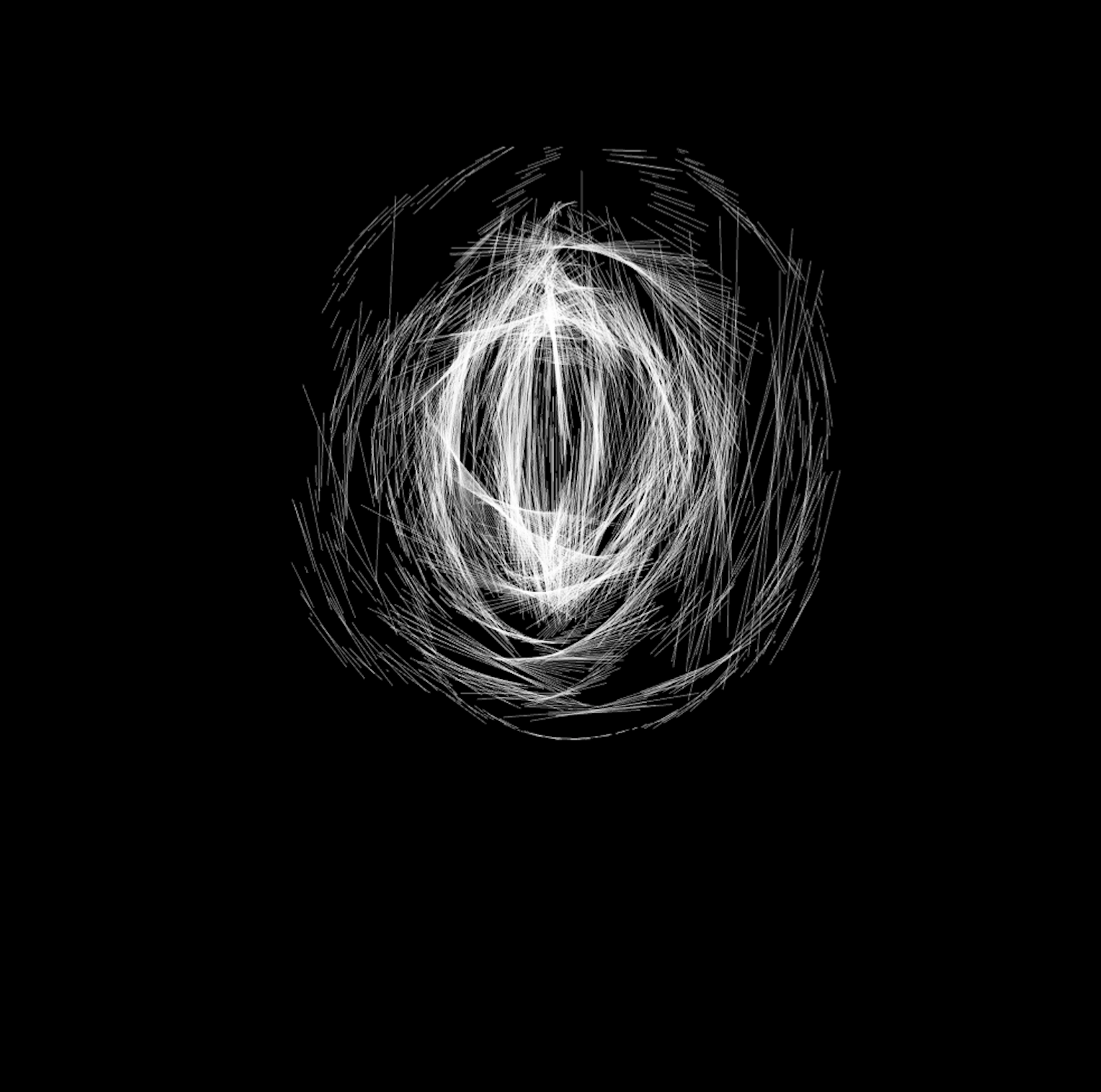
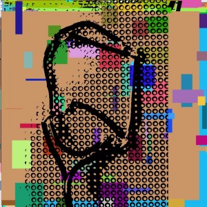
The values alter the drawing by changing the lengths of the lines being created, and if there is a drastic change it will alter the direction they are placed as well. For example, If you try the code in a darker room, the lines will be printed shorter, and in a lighter room they will be much longer. You can play with this to get some variations, such as:
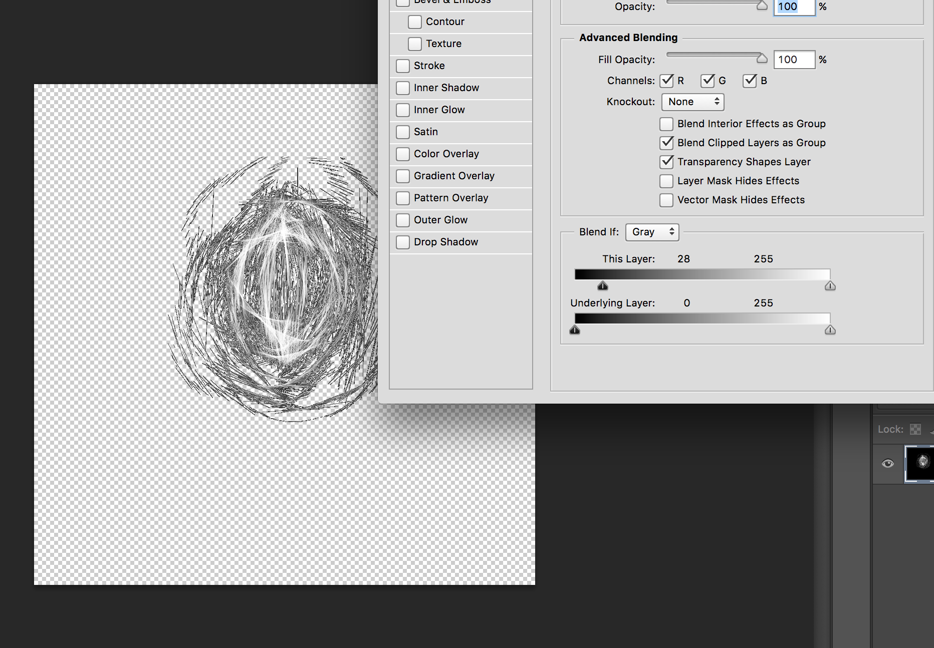
Afterwards, I decided to print them onto a black tote bag that I have using a fabric printer. To do that, you have to remove the background in Photoshop before printing (unless you want to keep the black background and print it on something else). To do this, simply double click on the layer and the blending settings will pop up. Under “Advanced blending” drag the arrow on the black side of the gradient towards the center–that way, all of the values darker than that will be removed from the image.
After you have your file ready, you are ready to fabric print! Press the fabric and add a fabric fixative to help the ink set in, put it in the printer and go! (or ask Amaury to help you)
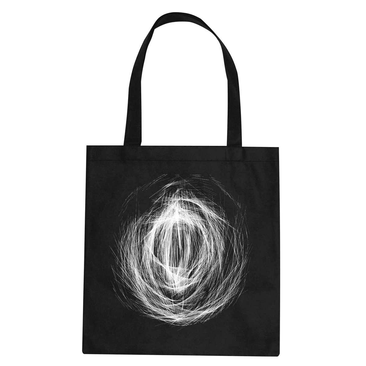
Unfortunately I can’t print it yet because I am waiting for the fabric primer to arrive in order to print on the fabric that I have, but when I do it will look something like this.
import cc.arduino.*;
import org.firmata.*;
import processing.video.*;
import processing.serial.*;
Serial myPort; // Create object from Serial class
int val; // Data received from the serial port
Capture video;
int a = 1024; // width of window
int b = 768; // height of window
int x = 100; // x- position text
int y = 700; // y- position text
int capnum = 0;
int countdowntimer = 10;
int globalframecount = 0;
PImage aj;
PImage bj;
PImage cj;
PImage dj;
color black = color(0);
color white = color(255);
int numPixels;
void setup() {
String portName = Serial.list () [2];
myPort = new Serial (this, portName, 9600);
print(Serial.list ());
frameRate (25);
size(1024, 768); // Change size to 320 x 240 if too slow at 640 x 480
strokeWeight(5);
// This the default video input, see the GettingStartedCapture
// example if it creates an error
video = new Capture(this, width, height, 30);
// Start capturing the images from the camera
video.start();
void draw() {
if ( myPort.available() > 0) {
val = myPort.read();
}
if (val>0) {
globalframecount = 1;
}
println(val);
if (video.available()) {
video.read();
video.loadPixels();
int threshold = 127;
float pixelBrightness;
loadPixels();
for (int i = 0; i<numPixels; i++) {
pixelBrightness = brightness(video.pixels[i]);
if (pixelBrightness > threshold) {
pixels [i] = white;
} else {
pixels[i] = black;
}
}
updatePixels();
int testValue = get(mouseX, mouseY);
float testBrightness = brightness(testValue);
if (testBrightness > threshold) { // If the test location is brighter than
fill(black); // the threshold set the fill to black
} else { // Otherwise,
fill(white); // set the fill to white
}
case ‘t’:
//null
break;
default:
//println(“Zulu”); // Prints “Zulu”
break;
}
if (globalframecount == 25) {
countdowntimer = 9;
}
if (globalframecount == 50) {
countdowntimer = 8;
}
if (globalframecount == 75) {
countdowntimer = 7;
}
if (globalframecount == 100) {
countdowntimer = 6;
}
if (globalframecount == 125) {
countdowntimer = 5;
}
if (globalframecount == 150) {
countdowntimer = 4;
}
if (globalframecount == 175) {
countdowntimer = 3;
}
if (globalframecount == 200) {
countdowntimer = 2;
}
if (globalframecount == 225) {
countdowntimer = 1;
}
// image (video, 0, 0);
if ((globalframecount < 250) & (globalframecount > 0)) {
textFont(fontA, 30);
fill(0);
text (“Preview! Get ready for your photo in “+str(countdowntimer), x+2, y);
text (“Preview! Get ready for your photo in “+str(countdowntimer), x, y+2);
text (“Preview! Get ready for your photo in “+str(countdowntimer), x-2, y);
text (“Preview! Get ready for your photo in “+str(countdowntimer), x, y-2);
textFont(fontA, 30);
fill(255);
text (“Preview! Get ready for your photo in “+str(countdowntimer), x, y);
//text (countdowntimer, width-250, y);
globalframecount++;
}
For this last exercise, I wanted to develop a project I made last Semester. It was about representing my family tree in a new way, using the zodiac sign’s constellation of each member of my family. I represented them all using in total 52 LEDs that represented the constellations of these zodiac signs : Leo, Aquarius, Pisces, Virgo, Sagittarius, Libra.
Here’s a picture of the work I made earlier:
I took pictures of each constellations and created patterns on Illustrator:
Arie
Sagittarius
Virgo
Pisces
I re-used the 52 LEDs and connected them to a Lylipad. The goal was to be able to control the intensity of the lights. And depending on the intensity, one of the 7 drawings (see above) would appear on the Processing code I made. It generates colorful drawings at a certain speed.
Finally, I decided to print them on fabrics following the idea that even though we can share the same Zodiac Sign we are all different and we all interpret it differently. That’s why the representation of each zodiac sign can never be the same.
For this assignment I want to make a T-shirt full of flowers to create a spring vide T-shirt for the spring. When the winters coming springs are not far….
So by create a model of print picture with full of flowers i start with processing.
Then push play we have the print picture with full of flowers for the shirt.
Because the colors and sizes are random so every time we play it and get the print picture will look different, so each of the flower vibe T-shits will be one and only.
Then add more designs on the shirt . And print it out.
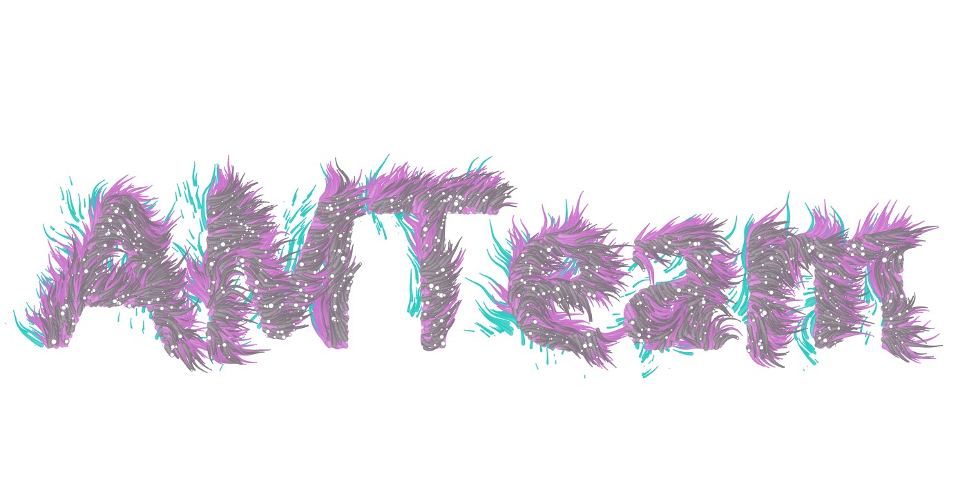
For this flip flop project I started with a lilypad and a code that I found online and then modified. The code creates generated hair-like text.
I wanted to use light sensors to control the code. One light sensor would restart the generative text, going through 4 different versions of movement and 4 different colors, the other sensor would change the colors by making them lighter or darker depending on the light value.
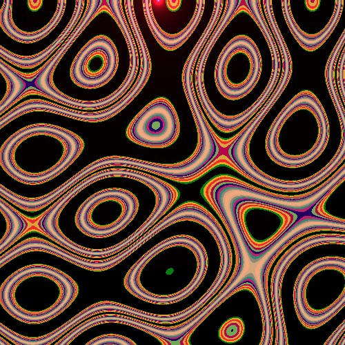
These are the kind of graphics that I ended up with and I created 12 different ones to then print on T-shirts.
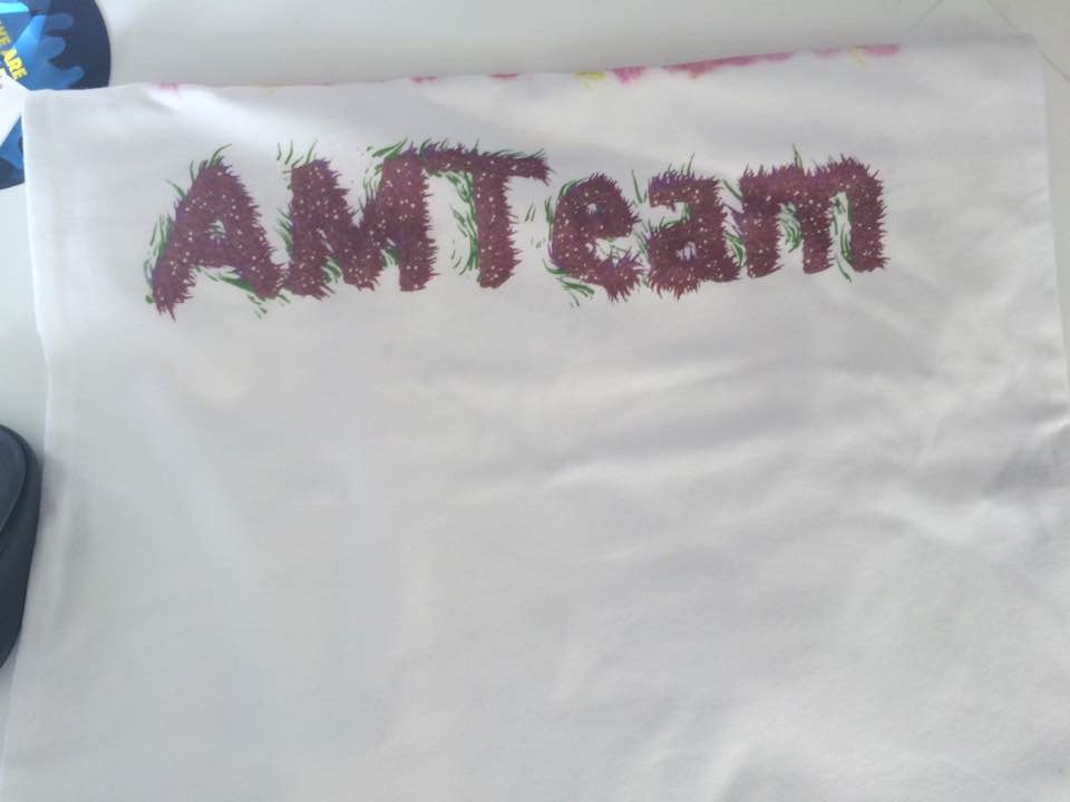
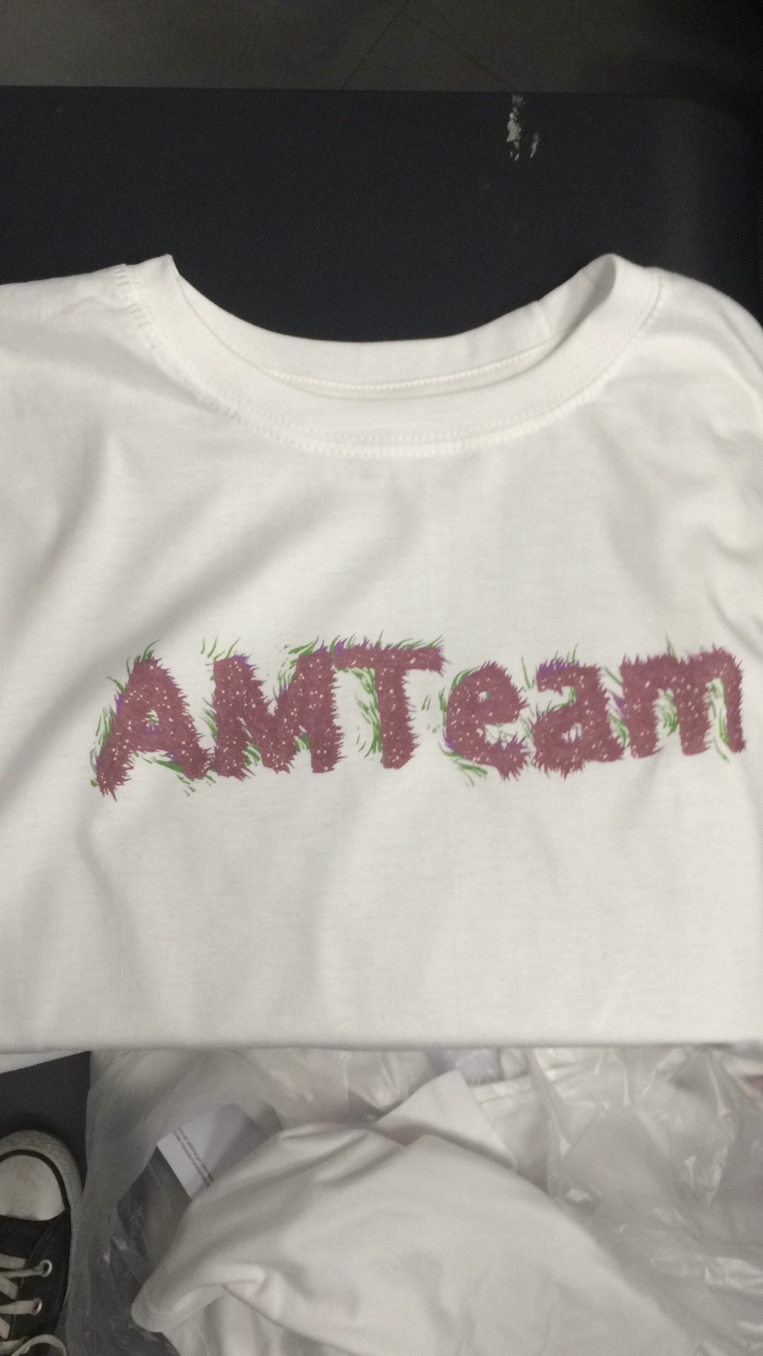
Here are some of the process pictures of the shirts after printing:
Code:
import processing.pdf.*;
import processing.serial.*;
import cc.arduino.*;
Arduino arduino;
int lightReading=0;
int lightReading2=0;
int maxParticles = 1000; // the maximum number of active particles
ArrayList <Particle> particles = new ArrayList <Particle> (); // the list of particles
int drawMode = 0; // cycle through the drawing modes by clicking the mouse
int colorMode = 0;
color BACKGROUND_COLOR = color(255);
color PGRAPHICS_COLOR = color(255);
float fc001;
PGraphics pg;
color c;
int number;
void setup() {
size(1400, 720, P2D);
smooth(16); // higher smooth setting = higher quality rendering
// create the offscreen PGraphics with the text
pg = createGraphics(width, height, JAVA2D);
pg.beginDraw();
pg.textSize(300);
pg.textAlign(CENTER, CENTER);
pg.fill(PGRAPHICS_COLOR);
pg.text(“AMTeam”, pg.width/2, pg.height/2);
pg.endDraw();
background(BACKGROUND_COLOR);
arduino = new Arduino(this, Arduino.list()[1], 57600);
arduino.pinMode(2, Arduino.INPUT);
arduino.pinMode(3, Arduino.INPUT);
}
void draw() {
lightReading=arduino.analogRead(3);
fc001 = frameCount * 0.01;
addRemoveParticles();
// update and display each particle in the list
for (Particle p : particles) {
p.update();
p.display();
}
if (lightReading <600) {
drawMode = ++drawMode%4; // cycle through 4 drawing modes (0, 1, 2, 3)
colorMode = ++colorMode%4;
//stroke(color(random(255), lightReading2/4, random(255), 125));
background(BACKGROUND_COLOR); // clear the screen
// Set color
//colorMode = (int) random(4);
if (drawMode == 2) image(pg, 0, 0); // draw text to the screen for drawMode 2
//particles.clear(); // remove all particles
delay(100);
}
println();
switch(colorMode) {
case 0:
c = color(lightReading2/4, 3, 16, 125);
break;
case 1:
c = color(155, lightReading2/4, 17, 125);
break;
case 2:
c = color(lightReading2/4, 87, lightReading2/4, 125);
break;
default :
c = color(183, 207, lightReading2/4, 125);
}
//colorChange();
// update and display each particle in the list
for (Particle p : particles) {
p.update();
p.display();
}
//if (lightReading <500){
//colorMode = ++colorMode%4; // cycle through 4 drawing modes (0, 1, 2, 3)
//background(BACKGROUND_COLOR); // clear the screen
////particles.clear(); // remove all particles
//delay(100);
//}
}
//void mousePressed() {
// drawMode = ++drawMode%4; // cycle through 4 drawing modes (0, 1, 2, 3)
// background(BACKGROUND_COLOR); // clear the screen
// if (drawMode == 2) image(pg, 0, 0); // draw text to the screen for drawMode 2
// //particles.clear(); // remove all particles
//}
void addRemoveParticles() {
//remove particles with no life left
for (int i=particles.size()-1; i>=0; i–) {
Particle p = particles.get(i);
if (p.life <= 0) {
particles.remove(i);
}
//for (int i=particles.size()-1; i>=0; i–) {
//Particle p = particles.get(i);
//if (lightReading <800) {
// particles.remove(i);
//}
}
// add particles until the maximum
while (particles.size () < maxParticles) {
particles.add(new Particle(c));
}
}
Particle(int c) {
getPosition();
// set the maximum life of the Particles depending on the drawMode
switch(drawMode) {
case 0: maxLife = 1.25; break;
case 1: maxLife = 1.0; break;
case 2: maxLife = 0.75; break;
case 3: maxLife = 0.5; break;
}
// randomly set a life and lifeRate for each Particle
updateColor(c);
life = random(0.5 * maxLife, maxLife);
lifeRate = random(0.01, 0.02);
}
void updateColor(color col) {
c = col;
}
//void updateColor(int colorMode) {
//
//}
void update() {
// the velocity/direction of each Particle is based on a flowfield using Processing’s noise() method
// drawMode 0: no extras (an xy-position will always return the same angle)
// drawMode 1: dynamic noise (an xy-position will return a slightly different angle on every frame)
// drawMode 2: rotation (the angle of each xy-position is globally rotated)
// drawMode 3: dynamic noise + rotation (combines drawModes 1 & 2)
float angle = noise(loc.x * 0.01, loc.y * 0.01, drawMode==1 || drawMode==3 ? fc001 : 0) * TWO_PI;
PVector vel = PVector.fromAngle(angle + (drawMode==2 || drawMode==3 ? fc001 : 0));
loc.add(vel);
life -= lifeRate; // decrease life by the lifeRate (the particle is removed by the addRemoveParticles() method when no life is left)
}
void display() {
//fill(255); // white fill
//stroke(lightReading2/4, 70, 120, 125);
stroke(c);
float r = 8 * life/maxLife; // radius of the ellipse
ellipse(loc.x, loc.y, r, r); // draw ellipse
}
// get a random position inside the text
void getPosition() {
while (loc == null || !isInText (loc)) loc = new PVector(random(width), random(height));
}
// return if point is inside the text
boolean isInText(PVector v) {
return pg.get(int(v.x), int(v.y)) == PGRAPHICS_COLOR;
}
}
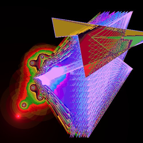
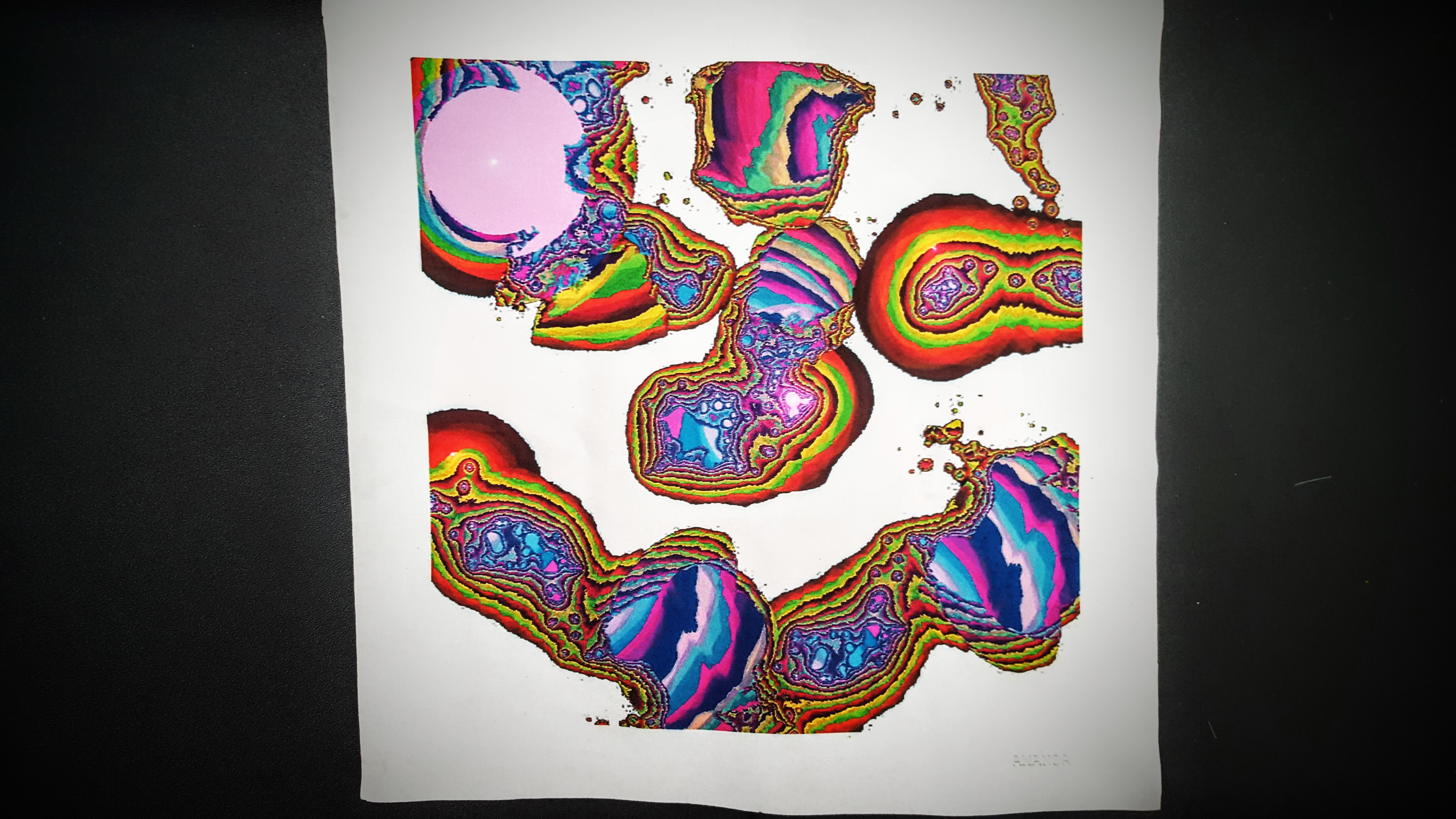
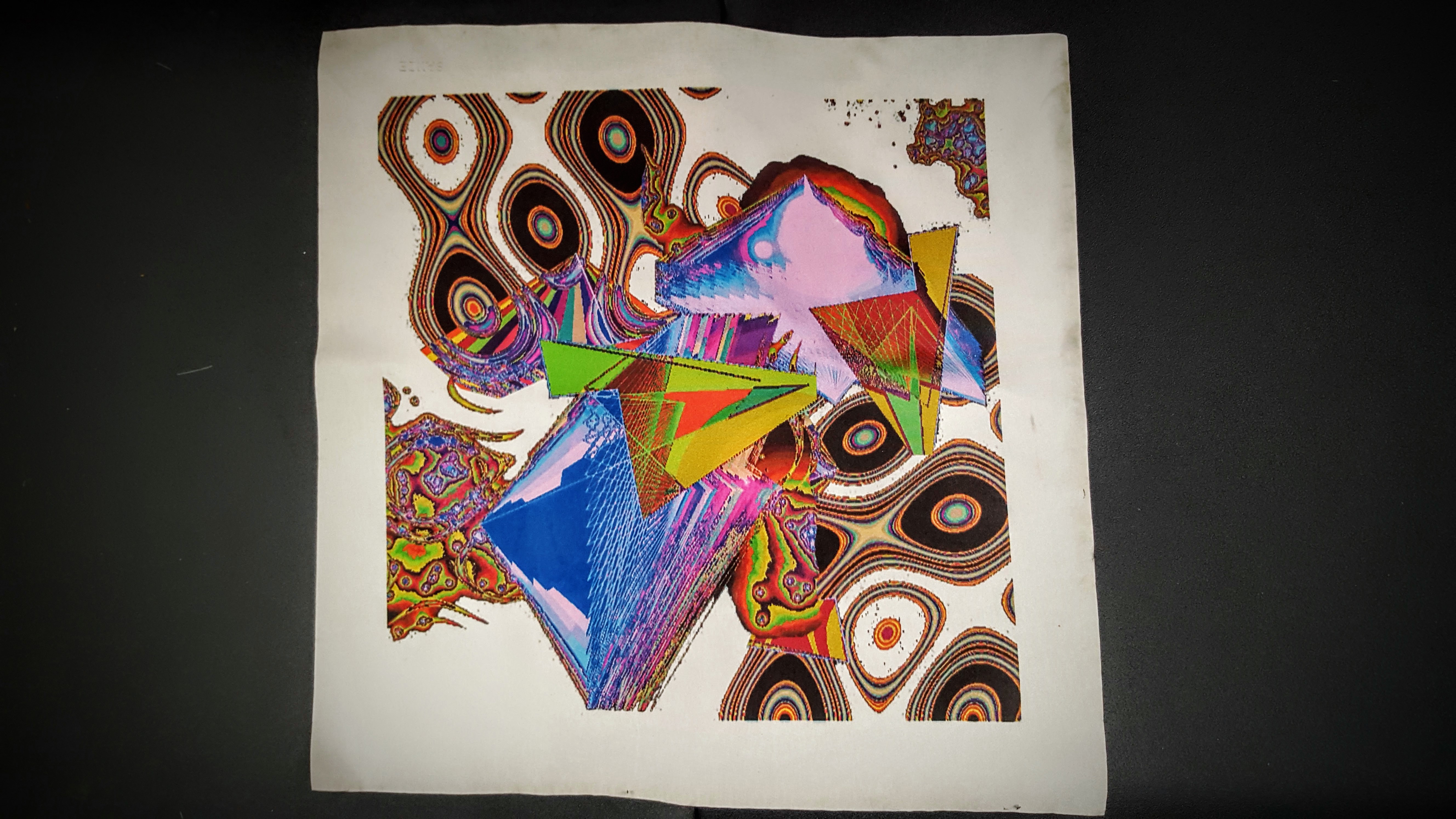
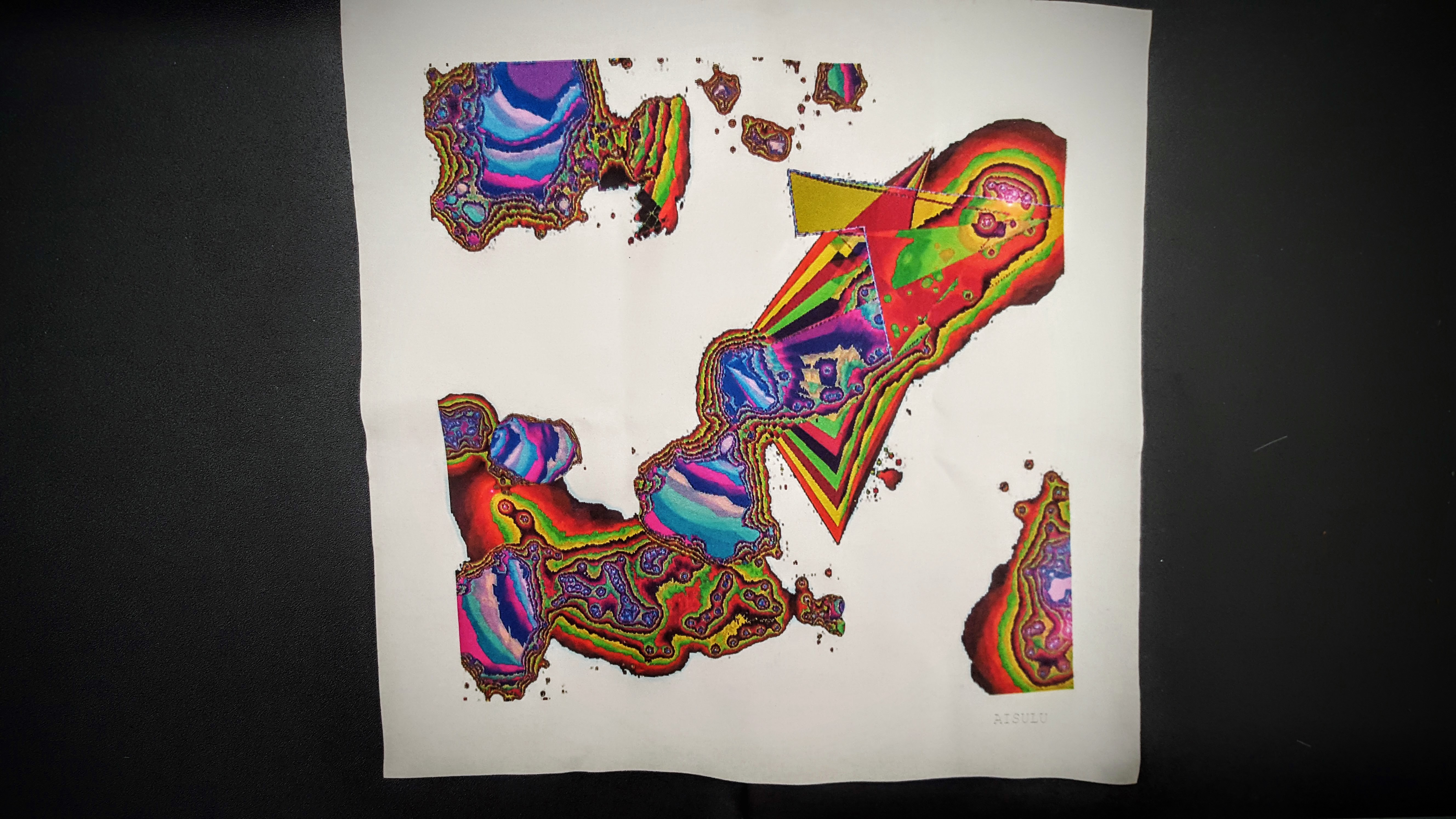
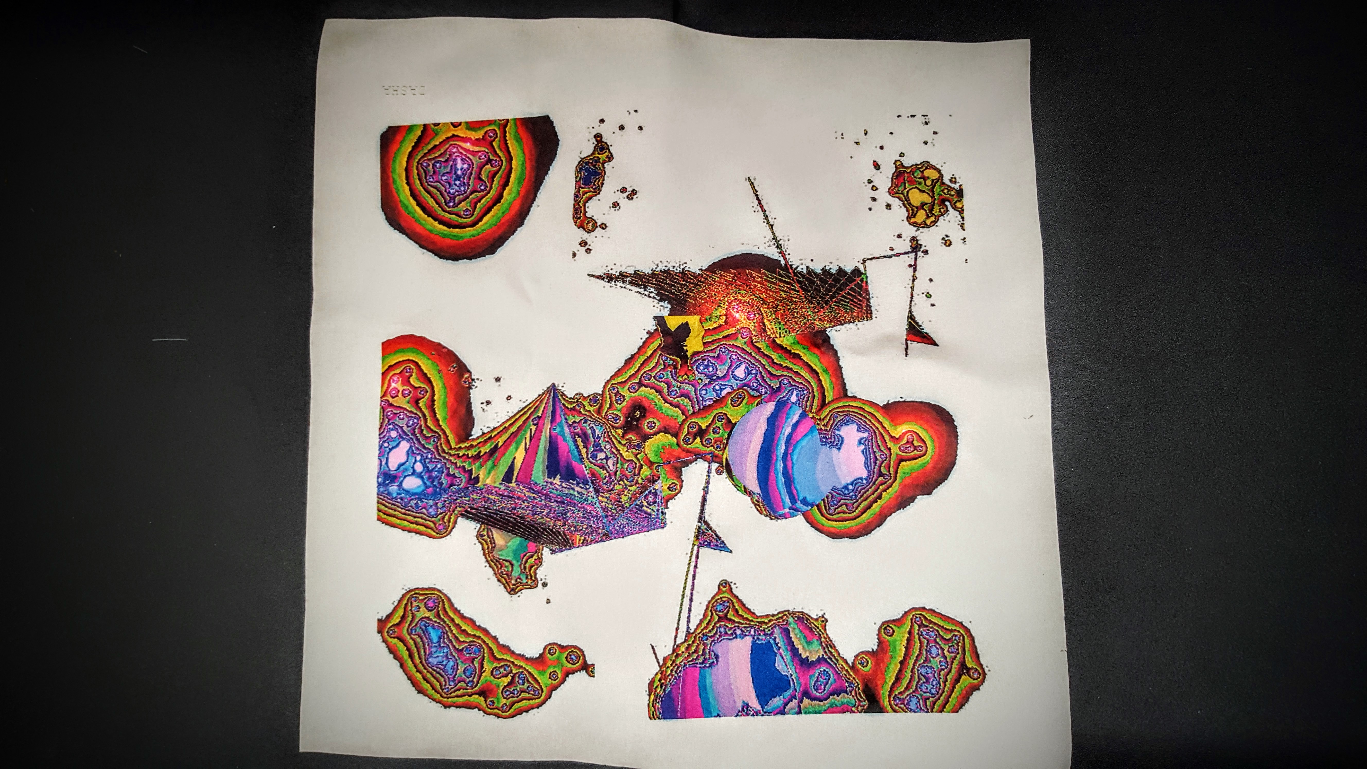
For this project, I created a Breathalyzer which draws colorful shapes as you exhale on it. The drawings vary depending on whether you had alcohol or smoked before.
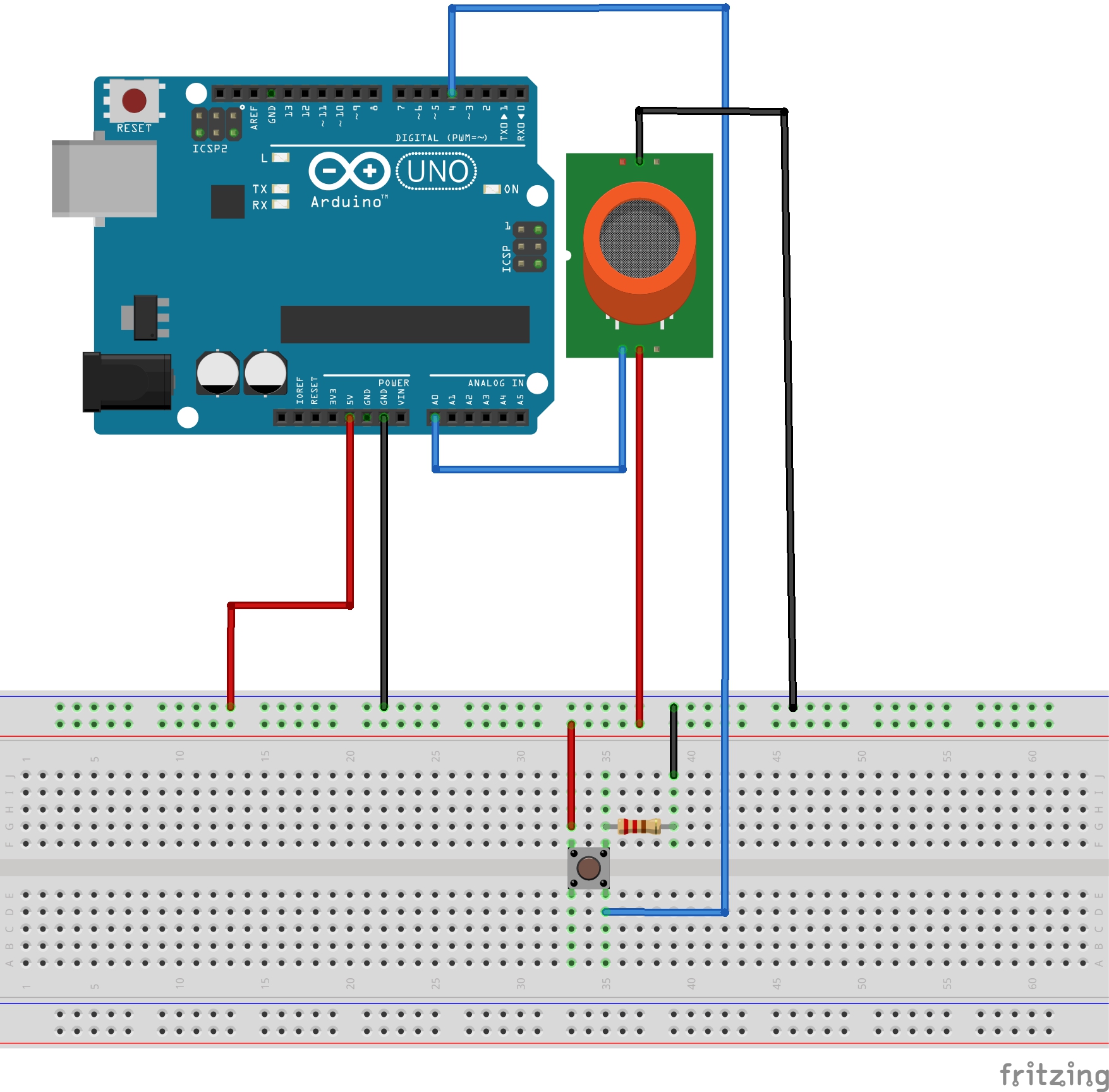
I used an MQ2 gaz sensor, a pushbutton, an arduino and processing.
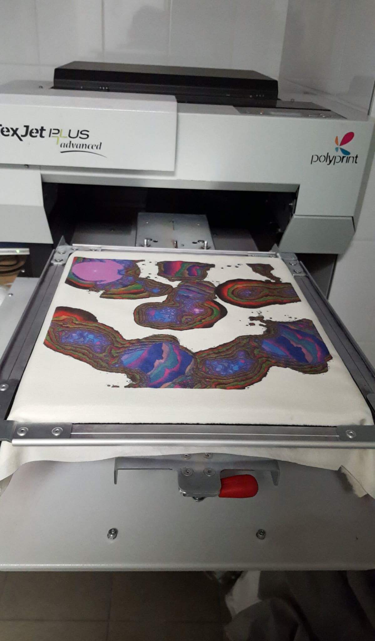
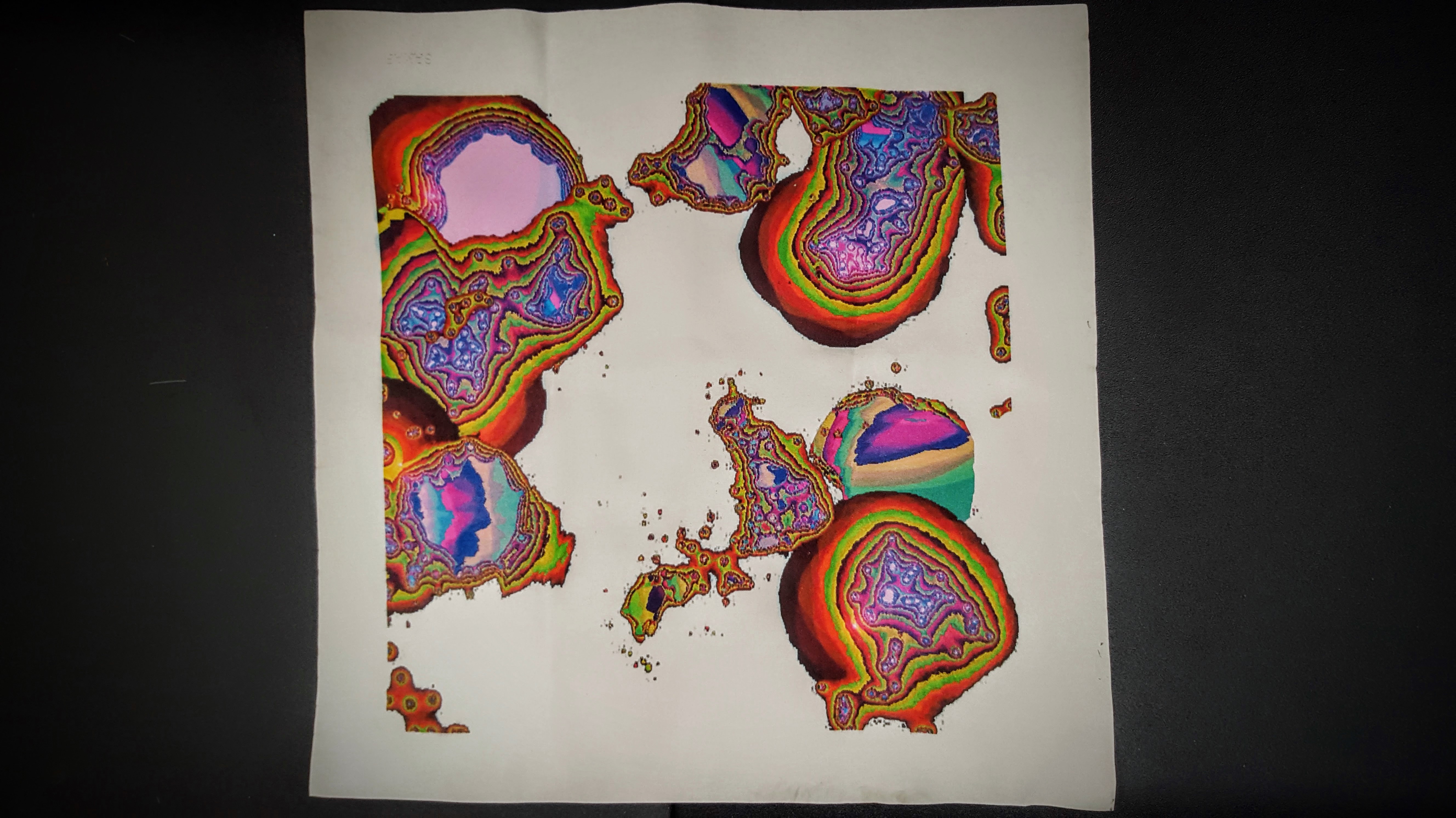
After saving a few of everyone’s breath drawings, I reassembled them in one file, which I printed on fabric to use as handkerchiefs.
Alcohol Value Reached
Decreasing Value From Alcohol to Normal
Smoke Value Reached
Breath Without Alcohol or Smoke.
I lasercut a box to put the sensor, adding a button that when pressed saves the screenshot.
Another hole on the side is used to pass the arduino serial cable.
The connexions to the MQ2 are as follow. My sensor had a four connexions: VCC (5V), GND, SIG (A0 pin) and NC. NC doesn’t need to be connected. The resistor used for the button is 10k Ohms.
After saving the images and recomposing them, the final result is printed on fabric (I used polyester).
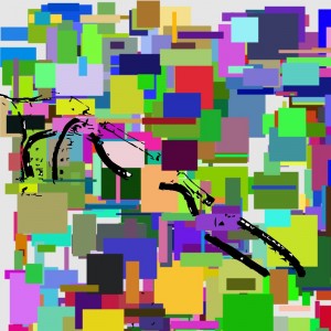
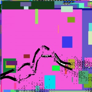
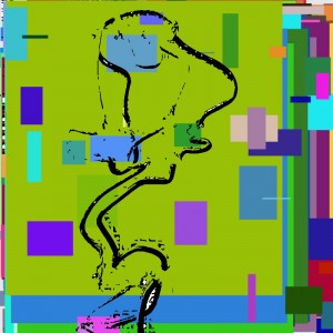
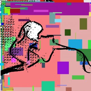
For the flip flop project I programmed a pulse sensor to initiate a processing sketch. The concept of this project was to emulate an internal self portrait. The idea is that you are drawing with your heart.
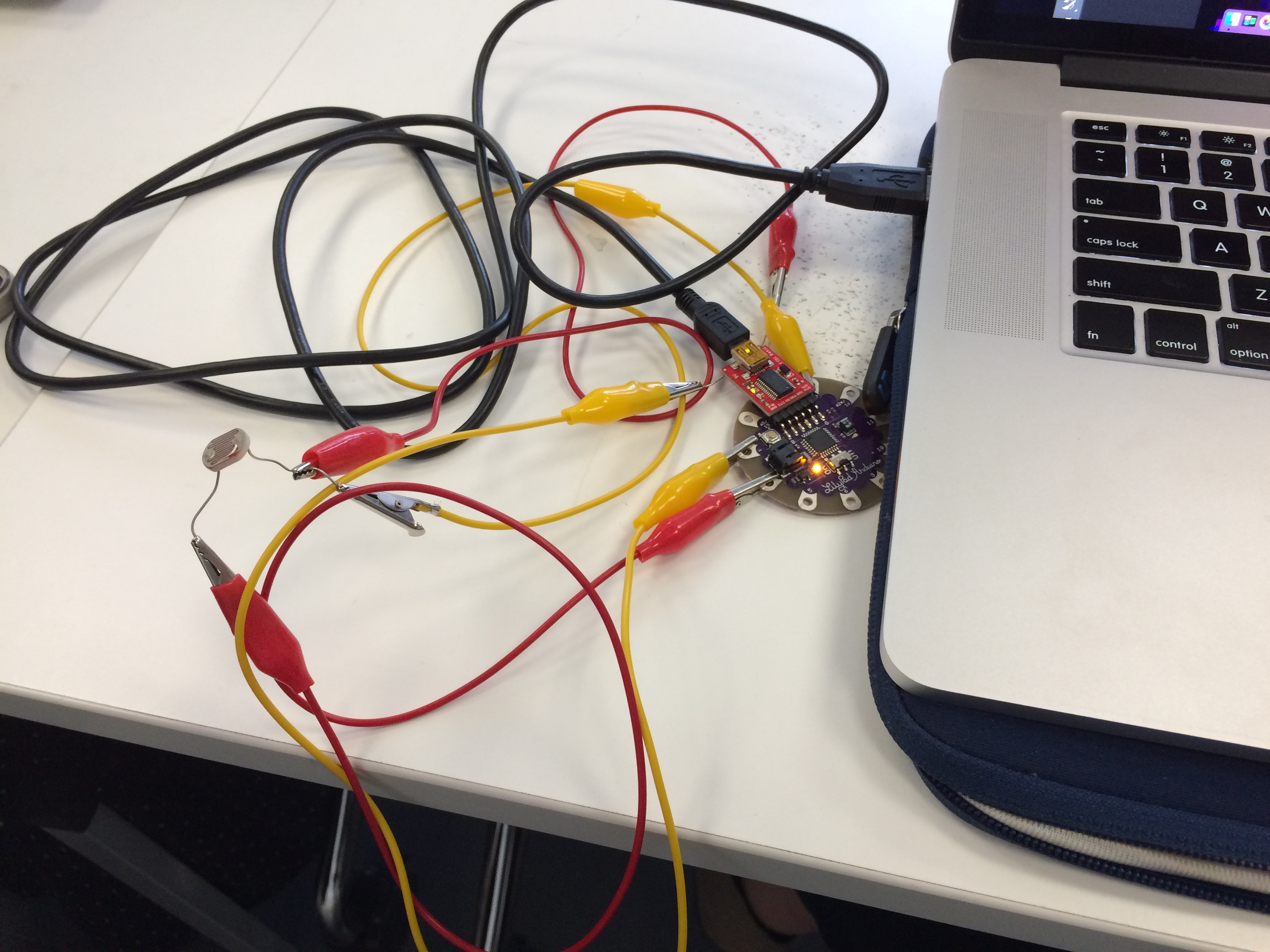
Step 1. Connect the heart sensor to an Arduino, and begin working on the code. The pulse sensor I used can be found here [you can also find the code to get started on their site]. To connect the pulse sensor, connect the black wire into ground, and the red into 5V, and the purple into A3.
Step 2. Once the pulse sensor is detected and you are able to receive information in the console, link to processing.
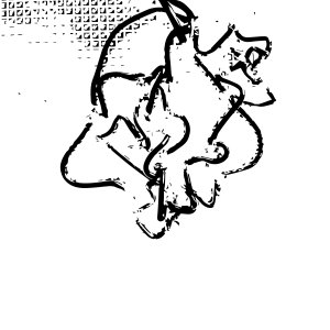
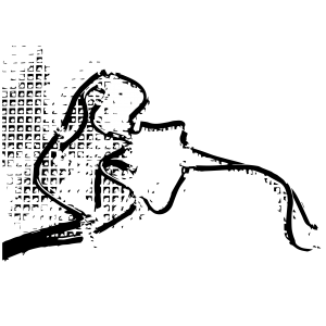
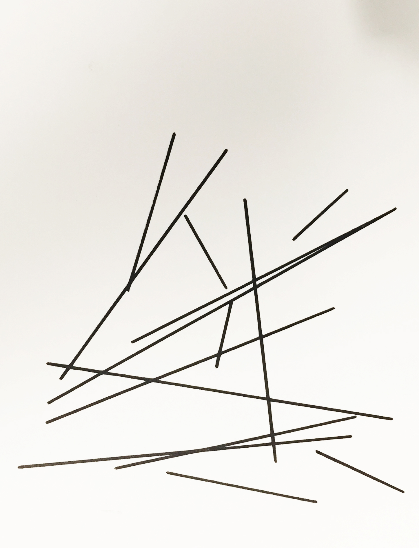
Step 3. Creating a sketch in processing. I really wanted the sketch to be minimal so I decided to do a simple sketch. For every heart beat detected, a random line is drawn.
Step 4. I quickly learned that the pulse sensor was not the most accurate sensor, so in order to get rid of ghost heart beats, I put in a line of code to filter out phantom beats.
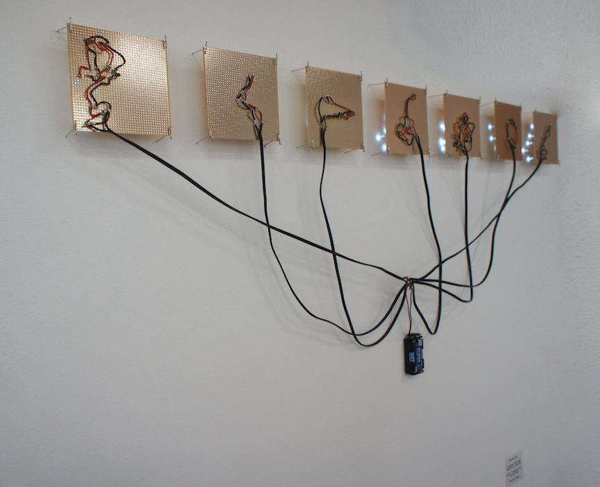
Now that the code is all set it was time to add another element of flipping and flopping. Initially we have a physical interaction of a person wearing a pulse sensor – which is also a digital experience. We take the measure of the physical world and interpret it via a sketch, and lastly we take the sketch and bring it back into the physical world. You can find the steps for that below:
Step 1: Wear the pulse sensor and begin drawing with your pulse.
Step 2: Open the automatically saved PDF, from your code’s folder, and import it into Illustrator.
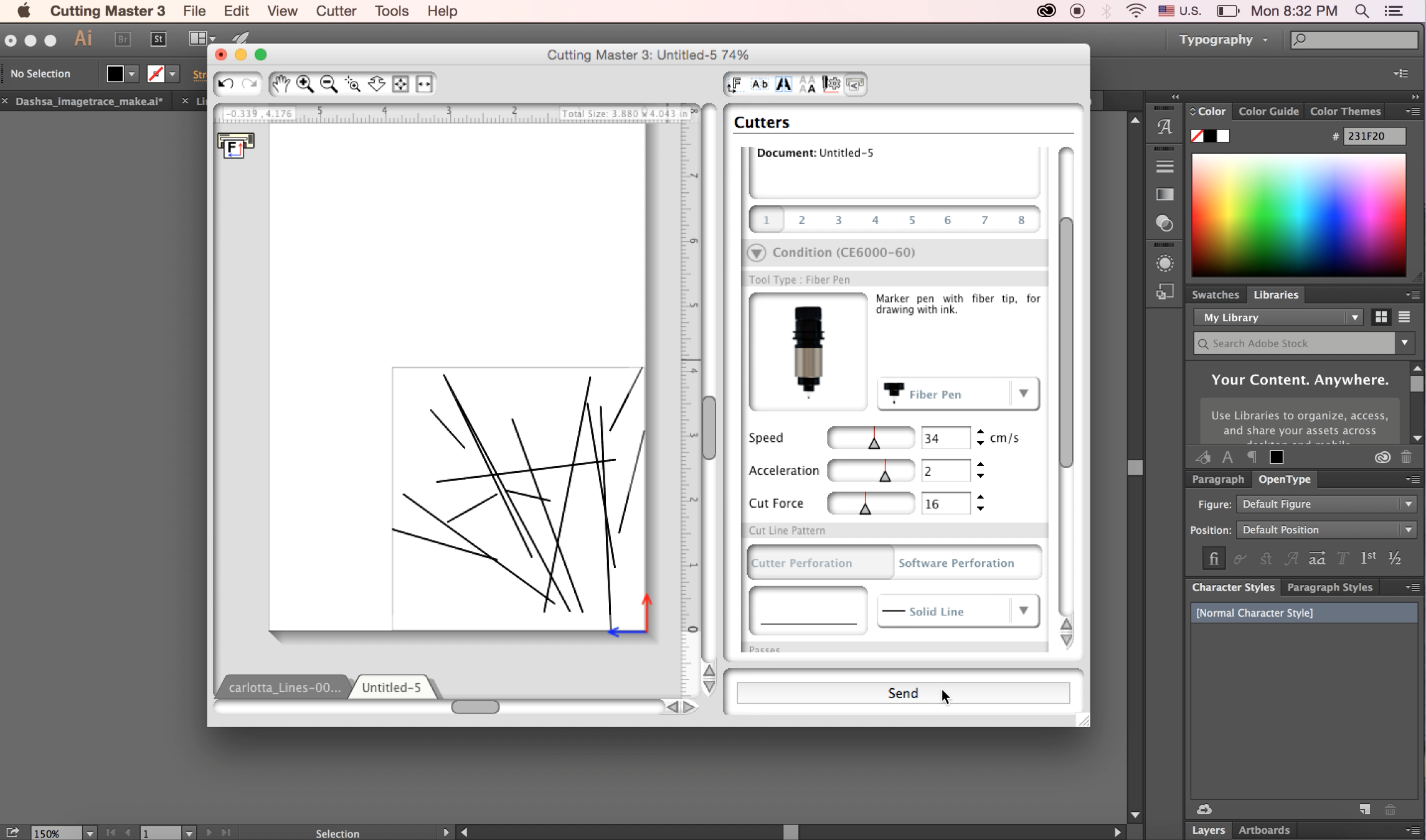
Step 3: In Illustrator expand, rasterize and image trace your file.
Object > Expand
Object > Rasterize
Object > Image Trace > Make and Expand
Step 4; Print on Cutting Master 3 with any type of writing utensil . In this case I used a fine point Staedtler pen. Below are the settings I used; speed: 34, acceleration: 2, cut force: 16.
Below is a quick video demonstrating the plotter in action!
For the flip flop project, I decided to create a generative design in Processing, utilize a sensor with the lilypad, and then ultimately produce a puzzle-with a piece for each of my classmates-out of my design.
So, I first found a code for a generative pattern to be created. I found a very simple one that just created rectangles and circles, and so when you pressed on the sensor, a rectangle is created, and more are produced depending on how hard you press on the sensor. Also, when you move the mouse, circles are created, just adding another element to the design.
Here is the Lilypad and sensor I used:
Here is a video of the sensor to Processing process:
void draw() {
// Call the variableEllipse() method and send it the
// parameters for the current mouse position
// and the previous mouse position
value=arduino.analogRead(3);
variableEllipse(mouseX, mouseY, pmouseX, pmouseY);
fill(random(0,800), random(0,30), random(0,500),value/4);
rect(value/4,mouseX,200,20);
}
// The simple method variableEllipse() was created specifically
// for this program. It calculates the speed of the mouse
// and draws a small ellipse if the mouse is moving slowly
// and draws a large ellipse if the mouse is moving quickly
void variableEllipse(int x, int y, int px, int py) {
float speed = abs(x-px) + abs(y-py);
ellipse(x, y, speed, speed);
}
and this:
import cc.arduino.*;
import org.firmata.*;
// setup – runs one time
void setup()
{
// set a stage size of 500 x 500 pixels
size (500,500);
// smooth all drawing
smooth();
// don’t draw an outline around your shapes
noStroke();
// draw all ellipses from their center point
ellipseMode(CENTER);
}
// draw – runs once a frame
void draw()
{
// fill all shapes with a solid black color with a very low opacity
fill(0,0,0,10);
// draw a rectangle that fills the whole screen
// don’t draw this rectangle if you don’t want to erase the screen each time
rect(0,0,width,height);
// fill all shapes with a white color from this point forward
fill(255);
// draw a small ellipse (20×20) where the mouse is
ellipse(mouseX, mouseY, 20, 20);
}
So, once I came up with a sketch that I thought looked aesthetically pleasing, I took a screenshot, cropped it, and put it into Illustrator to create a puzzle. It is a tangram-type puzzle, and here is what the final looked like:
I then wanted to laser cut each of the 12 pieces so everyone could have one, but I left Paris before I could, so I am extremely grateful to Ivan and Martin who laser cut it for me. I don’t have the images (yet), but I am sure the laser cut pieces look great!
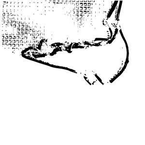
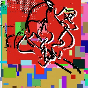
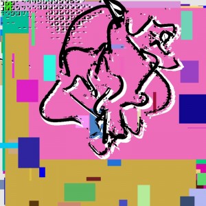
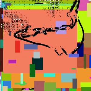
My project was inspired by Drake’s song Hotline bling. Instead of making colour changing backgrounds like the music video, you can dance to glitches instead. The idea is to dance with a light sensor attached lily pad, and change the projection colour by shining light onto the sensor. Most preferably with a mobile phone. Because, you know, it’s a song about a hotline/phone.
Process
Processing
First I had to write up the code for Processing. The idea behind this code, is to have two different colour glithces. The first one is for when sensor detects no light, and the other is for when it senses light. The code also records every single glitch into its processing folding. Which I will later use to make a flip book as the physical object.
The code is attached in my insturctables post.
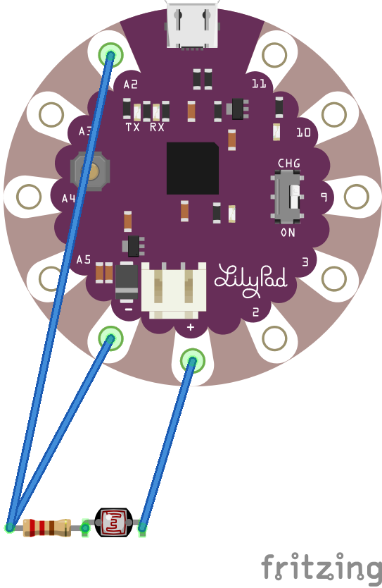
Lily Pad
After I have figured out the basic code for processing, I have figure out the lily pad connection with the sensor. So after testing a few times with different connections, I finalized a connection that would work with the lily pad. here is a graph of how it is being connected.
After that I had to upload the code on Arduino, so that it can link the lily pad with processing.
Setting up
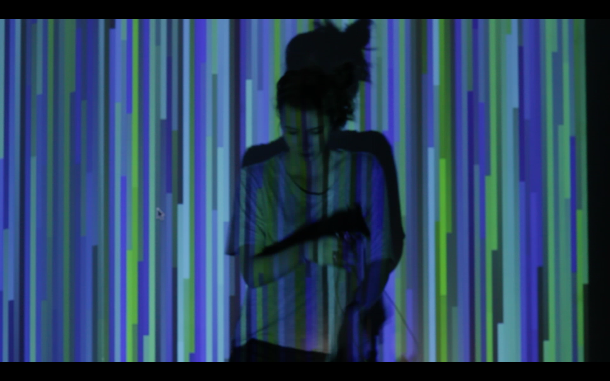
Setting up was easy. I just had to put a projector in front of a white wall after dark. I tried a few different distance and I think 15 feet is a good distance. The camera I used was a Canon 60D with a standard lens. A wide angle lens would have been even better. After a few test run projecting the glitches onto the wall and on Dasha( the greatest dancer!) We began to film.
Filming
So once Dasha is ready, I begin to play the song on my speakers, so she can dance to the beat, and there you go! The hotline bling glitch is complete!
Flip Book
Here is a video of the binding process with the same binder we have at school.
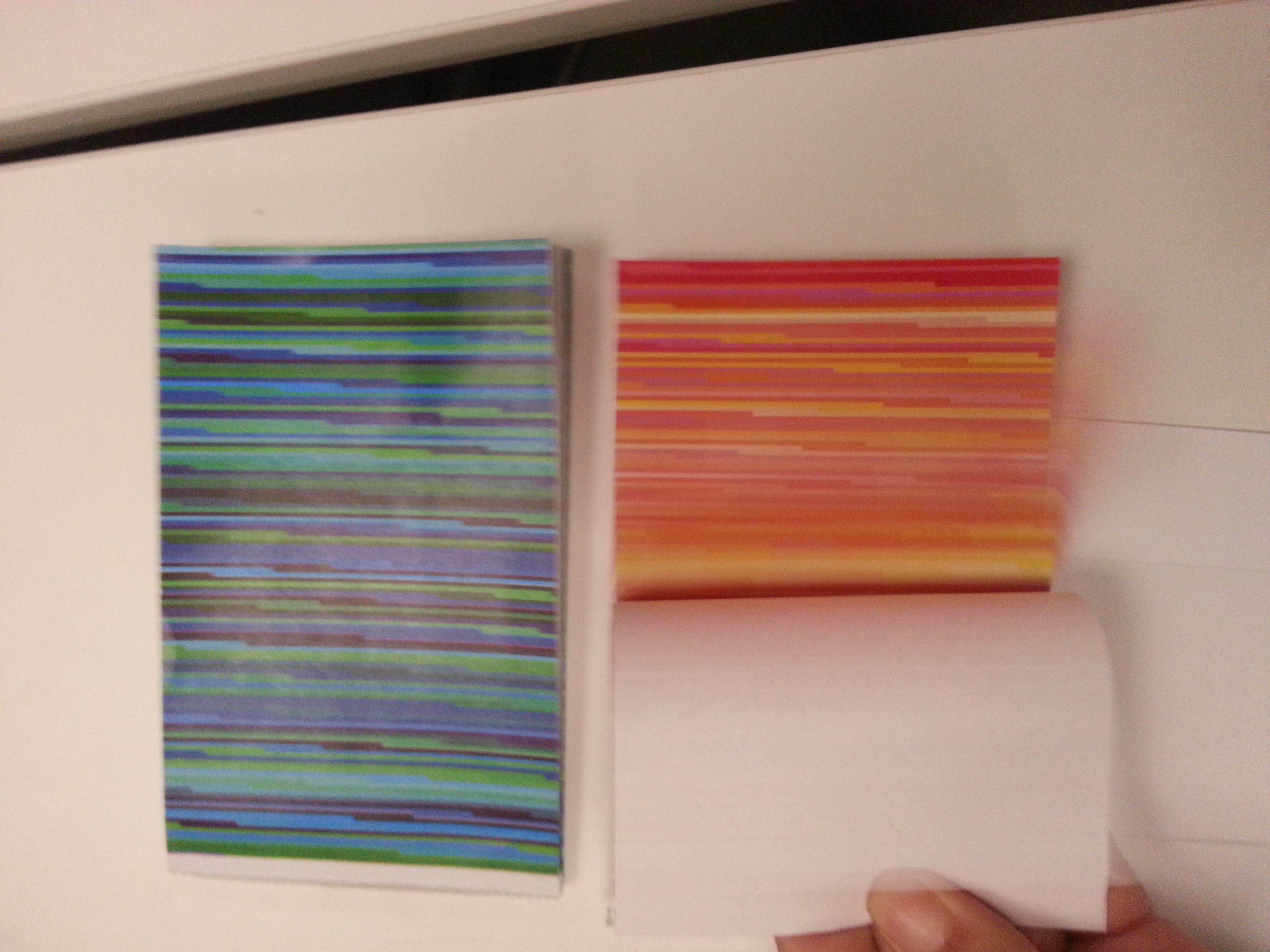
To make the physical object for the box, I collected all the glitches from the filming process, and separated them by colour. Then I printed them out, 4 per A4 paper. cut them out and made them into flip books.
Here are the two colours when I printed them.
Flipping through the books, to make it easy to flip the edges need to be cut properly. And turned out, the book was too big in size and it needed to be cut down for the actual box. So the final product isn’t the complete screen shot, but a fraction of it. Though if I have to do it again, I would print it small so each page is a complete screen shot.
Thoughts
This was a fun project, and I really enjoyed doing it. Not only was it something in trend, but it also includes my love for glitches. In the future, I would love to do more interactive projection art. It is the best kind of project when there can be participation from the audience! Also If I will continue on this project, I would make the light sensor easier to hold, because during filming, the biggest problem we had was the sensor falling off the lily pad. Perhaps I should make a box to contain it, so that it can stay intact when it is in use. All in all, I think this is one of my more successful project, and I am happy to share it with the internet. Below is a link to the insturctables website, I hope you will have fun making it too!