
For the first attempt, I sew the fabrics and sponges together inside a pocket I made.
So it didn’t work at all the first try, I later figured out it was because I sew all the parts together with unconductive thread. Also to mention about the design of the pocket, is for easier correction. I know I won’t get it right the first time, with the past few experiments taking much more time than I intended. So afterwards, I sew each conductive fabric onto one sponge, placed the resistive fabric in between and placed it back into the pocket. This time it worked much better.
Moving on to the speaker, first I built the circuit.

I planed to connect the circuit onto a t-shirt for the speakers, and so I tested it out. But unfortunately, there is a short circuit problem. The 555 heats up when I connect the battery to the circuit, but the speakers didn’t work. I have tried to redo the circuit but didn’t make any difference. The circuit itself is done as shown on the graph, so it is in the right order.
For now, I can only work in class to figure out the problem and redo it again later.
My final project is to create a stress relief game that focuses on releasing anger through motion rather than ‘cleansing the mind’ because that never worked for me. My inspiration came from years of practice in Thai boxing, it is my form of stress relief. When I box, I imagine my target as something that created my anger, by constantly attacking it, the adrenaline gives me an instant relief. So this game is aim for anyone who has the same problem as me – getting more stressful after yoga or meditation.
So I went online to search for stress relief games, they are either direct or not really marketed as a stress relief game.
http://games.co.za/smack-the-computer.html
This has been the longest stress relief game I have seen online, it was around since I was in primary school.

http://games.co.za/whack-your-boss.html
This is a game where you can find 16 ways to kill your boss.
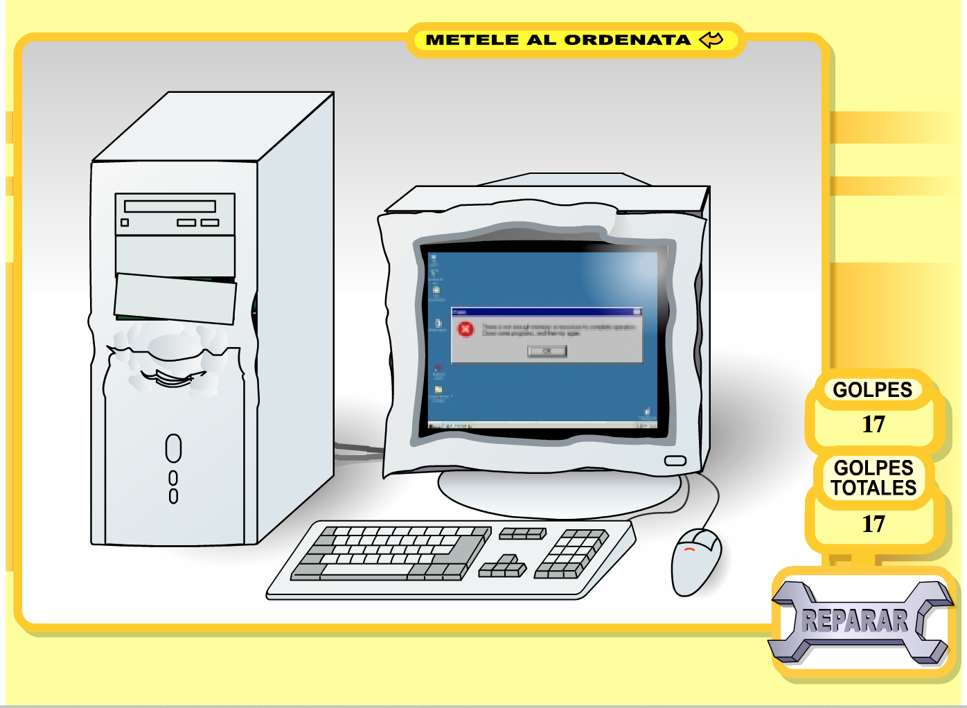
These two games have a common problem, the fact that they are controlled with the mouse and keyboard only, makes it lacking of a physical element. And the violence is not a very good message, targeting your negativity and trying to kill someone is two very different things. Of course many people just get lost in their favourite games to relief stress, I want to make a simple game that is effective.
I went with the idea of creating a simple game where you have to delete images on the screen with an accelerometer measuring your physical movement. The harder you wave, the more images will be deleted.
Process
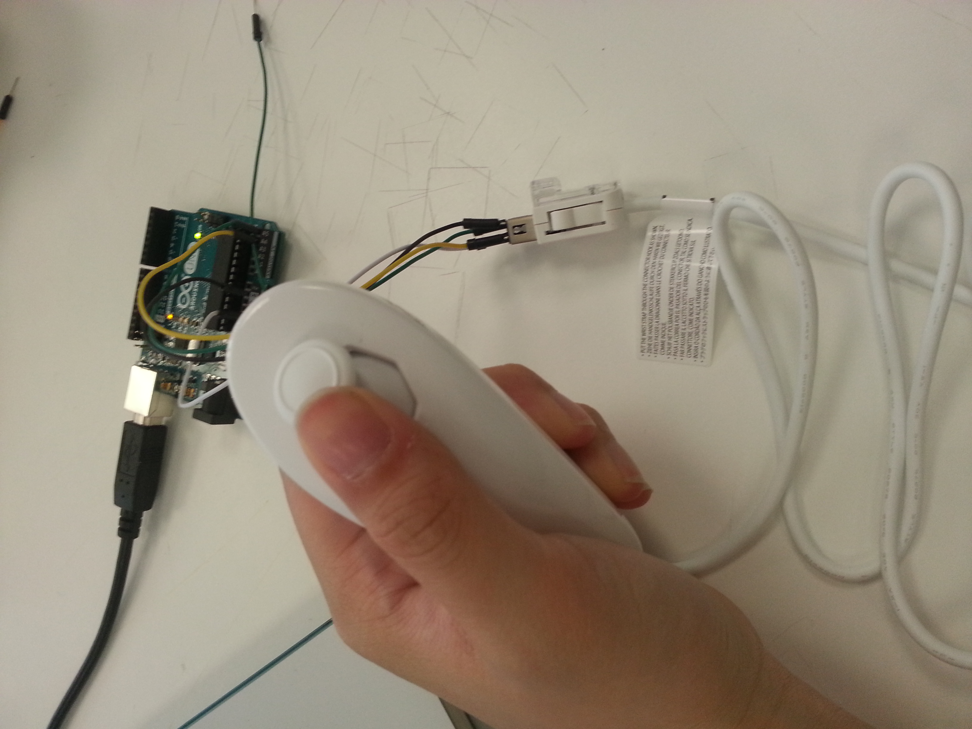
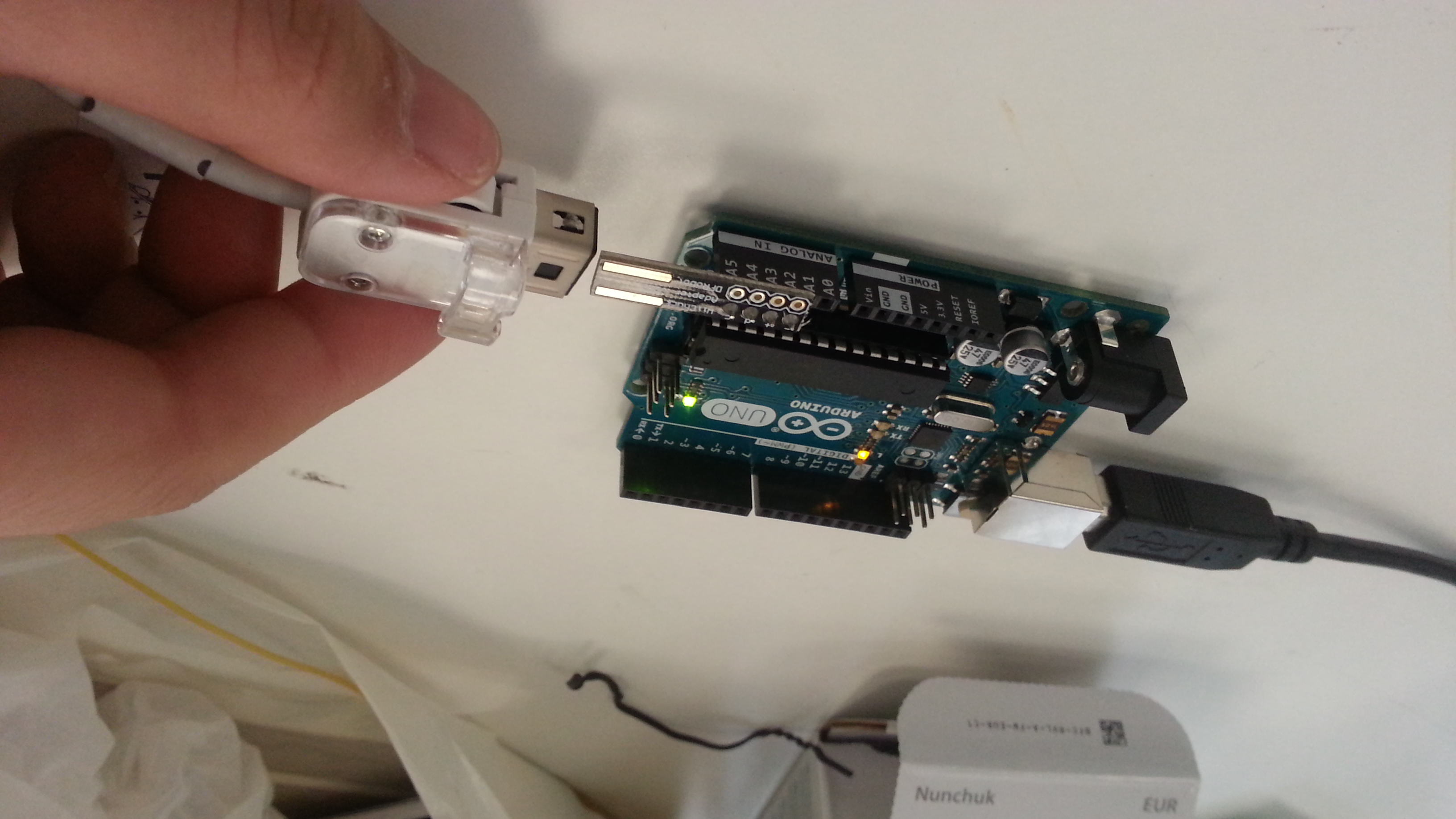
The first thing I did was to decide on the physical element I will be using in the project. My first idea was to use a spark fun accelerometer and create a controller. But after all the shipping delays, I came up with a better solution, which is a WII nunchuck. This is will allow maximum movement when playing the game, and it is easy to hold and control.
Then I worked on the code for the visuals. First, I tried to make a code with only shapes to simplify the process. Below are all the codes I have done.
//import processing.serial.*;
//import cc.arduino.*;
//Arduino arduino;
//int x, y;
//color start=color(0, 0, 0);
//color finish;
//float amt = 0.0;
//int value;
//void setup() {
// size(1100,700);
// //println(Arduino.list());
// //arduino = new Arduino(this, Arduino.list()[1], 57600);
// //arduino.pinMode(2,Arduino.INPUT);
//}
//void draw() {
//value = arduino.analogRead(2);
// for (x=0; x<=width; x+=8) {
// for (y=0; y<=height; y+=8) { // noStroke(); // fill(finish); // rect(x, y, 8, 8); // amt+=.01; // if (amt >= 1) {
// amt = 0.0;
// finish = color(value/4, random(255), random(255));
// }
// }
//println(value);
// }
// saveFrame(“line-######.png”);
//}
int value = 0;
void setup() {
fullScreen(2);
background(255);
loop();
stroke(0);
fill(200,388,47);
rect( random(1000), random(1000),100,100);
}
void draw(){
if (mousePressed == true){
noStroke();
fill(255);
rect( mouseX, mouseY,100,100);
}
else {
stroke(0);
fill(200,388,47);
rect( random(2000), random(2000),100,100);
}
}
//void mousePressed() {
// noStroke();
// fill(255);
// rect( mouseX, mouseY,100,100);
//}
//void mouseReleased() {
//}
int value = 0;
boolean fillIt = true;
void setup() {
fullScreen(2);
background(255);
loop();
stroke(0);
fill(200, 388, 47);
rect(random(width), random(height), 100, 100);
}
void draw() {
if (fillIt) {
stroke(0);
rectMode(CENTER);
fill(200, 388, 47);
rect(random(width), random(height), 100, 100);
if (isFilled()) {
fillIt = false;
}
}
else if (mousePressed == true) {
noStroke();
fill(255);
rectMode(CENTER);
rect( mouseX, mouseY, 100, 100);
if (isErased()) {
fillIt = true;
}
}
}
boolean isFilled() {
loadPixels();
for (int i=0; i<width*height; i++) {
if (pixels[i] == color(255)) {
return false;
}
}
return true;
}
boolean isErased() {
loadPixels();
for (int i=0; i<width*height; i++) {
if (pixels[i] != color(255)) {
return false;
}
}
return true;
}
//void mousePressed() {
// noStroke();
// fill(255);
// rect( mouseX, mouseY,100,100);
//}
//void mouseReleased() {
//}
import processing.serial.*;
Serial port; // Create object from Serial class
int val; // Data received from the serial port
int xAcc, yAcc, zAcc;
int value = 0;
boolean fillIt = true;
void setup() {
fullScreen(2);
background(255);
loop();
stroke(0);
fill(200, 388, 47);
rect(random(width), random(height), 100, 100);
frameRate(60);
// Open the port that the board is connected to and use the same speed (9600 bps)
println(Serial.list());
String portName = Serial.list()[1];
port = new Serial(this, portName, 115200);
}
void draw() {
if (fillIt) {
stroke(0);
rectMode(CENTER);
fill(200, 388, 47);
rect(random(width), random(height), 100, 100);
if (isFilled()) {
fillIt = false;
}
} else {
//if (mousePressed == true) {
readValues();
noStroke();
fill(255);
rectMode(CENTER);
float x = map(xAcc, -300, 300, 0, width);
float y = map(yAcc, -150, 150, 0, height);
rect( x, y, 100, 100);
if (isErased()) {
fillIt = true;
}
}
}
boolean isFilled() {
loadPixels();
for (int i=0; i<width*height; i++) {
if (pixels[i] == color(255)) {
return false;
}
}
return true;
}
boolean isErased() {
loadPixels();
for (int i=0; i<width*height; i++) { if (pixels[i] != color(255)) { return false; } } return true; } void readValues() { if (port.available() > 0) { // If data is available,
String val = port.readStringUntil(‘\n’); // read it and store it in val
if (val != null) {
// Split info (received as ie: 125;255)
val = trim(val);
String[] values = val.split(“,”);
if (values.length == 3) {
println(values[0], “/”, values[1], “/”, values[2]);
xAcc = Integer.parseInt(values[0]);
yAcc = Integer.parseInt(values[1]);
zAcc = Integer.parseInt(values[2]);
}
}
}
}
//void mousePressed() {
// noStroke();
// fill(255);
// rect( mouseX, mouseY,100,100);
//}
//void mouseReleased() {
//}
These are all codes that I have worked on for the visual part of the project. First I made the game control with the mousepad, to simplify the project. When I made sure it worked, I moved onto connecting the game with my WII nunchuck.
here are some photos of the process, I have tried two way of using the nunchuck.
Here is a link in insturctables that I referred to.
http://www.instructables.com/id/Arduino-Wii-Nunchuck-controller/?ALLSTEPS
Final thoughts:
The idea worked out quite differently than I imagined, it did not go as smooth as I thought it would be. At first I thought it would be a simple idea, but the accelerometer was harder to use than I thought. And during the process I have encounter so many problems with uploading the code to the nunchuck to actually make it work. I wish that I would have researched it a bit more before I decided to do this project, because I might have change my idea, use another controller, or do this project with someone else and not alone. With the controller keep falling off, I think it would work better if I got the bluetooth controller for the nunchuck, it would have given the user more freedom in using the controller, without worrying about it falling off the Arduino. If there is more time I would like to continue working on this project until I can make it work. Though the result is less than satisfying, I think i have learnt a lot during the process of trying to make it, and with this knowledge I will continue to build my future project with Arduinos to make motion sensing games.
My project was inspired by Drake’s song Hotline bling. Instead of making colour changing backgrounds like the music video, you can dance to glitches instead. The idea is to dance with a light sensor attached lily pad, and change the projection colour by shining light onto the sensor. Most preferably with a mobile phone. Because, you know, it’s a song about a hotline/phone.
Process
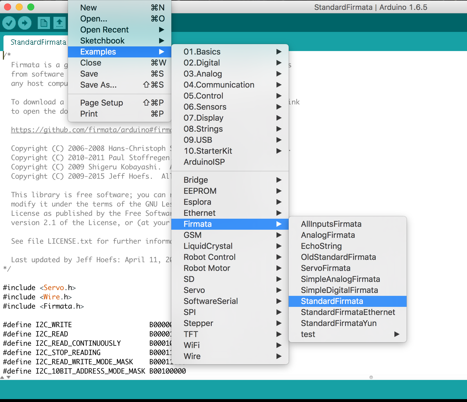
Processing
First I had to write up the code for Processing. The idea behind this code, is to have two different colour glithces. The first one is for when sensor detects no light, and the other is for when it senses light. The code also records every single glitch into its processing folding. Which I will later use to make a flip book as the physical object.
The code is attached in my insturctables post.
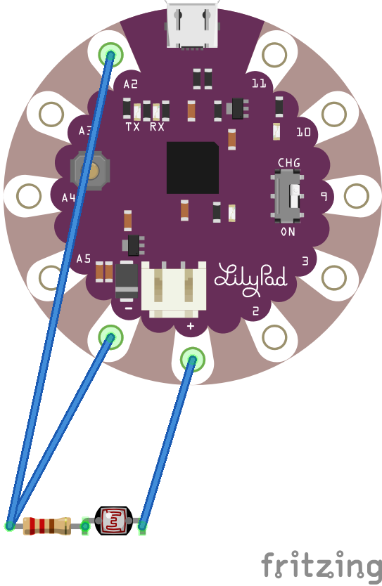
Lily Pad
After I have figured out the basic code for processing, I have figure out the lily pad connection with the sensor. So after testing a few times with different connections, I finalized a connection that would work with the lily pad. here is a graph of how it is being connected.
After that I had to upload the code on Arduino, so that it can link the lily pad with processing.
Setting up
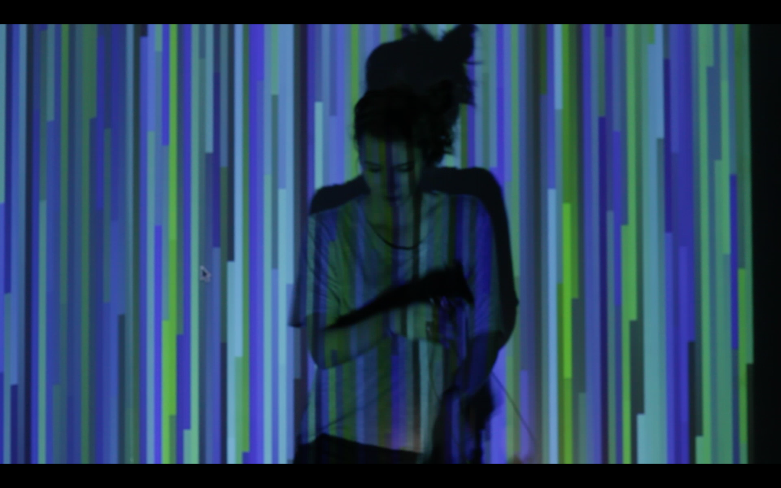
Setting up was easy. I just had to put a projector in front of a white wall after dark. I tried a few different distance and I think 15 feet is a good distance. The camera I used was a Canon 60D with a standard lens. A wide angle lens would have been even better. After a few test run projecting the glitches onto the wall and on Dasha( the greatest dancer!) We began to film.
Filming
So once Dasha is ready, I begin to play the song on my speakers, so she can dance to the beat, and there you go! The hotline bling glitch is complete!

Flip Book
Here is a video of the binding process with the same binder we have at school.
To make the physical object for the box, I collected all the glitches from the filming process, and separated them by colour. Then I printed them out, 4 per A4 paper. cut them out and made them into flip books.

Here are the two colours when I printed them.
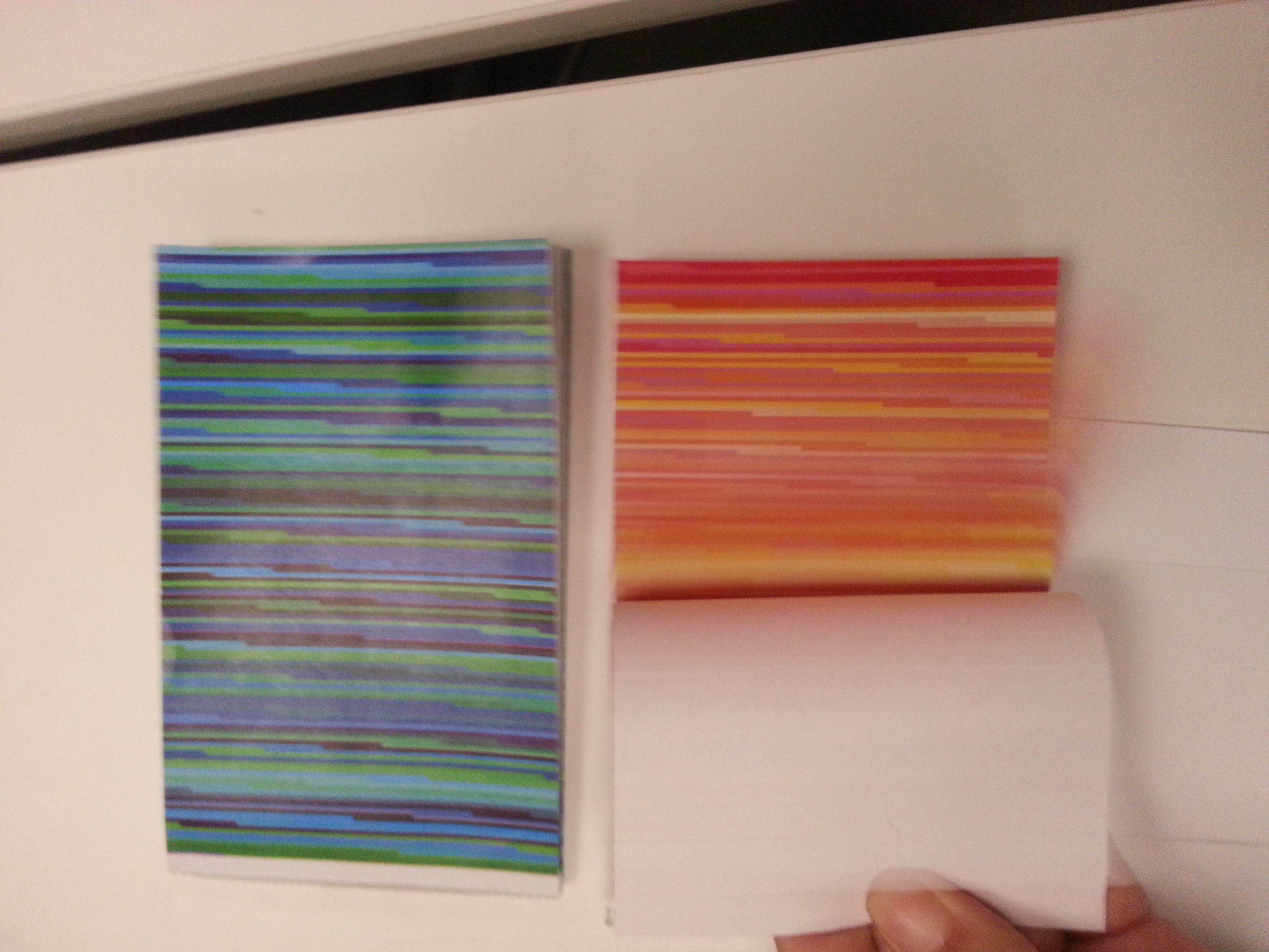

Flipping through the books, to make it easy to flip the edges need to be cut properly. And turned out, the book was too big in size and it needed to be cut down for the actual box. So the final product isn’t the complete screen shot, but a fraction of it. Though if I have to do it again, I would print it small so each page is a complete screen shot.
Thoughts
This was a fun project, and I really enjoyed doing it. Not only was it something in trend, but it also includes my love for glitches. In the future, I would love to do more interactive projection art. It is the best kind of project when there can be participation from the audience! Also If I will continue on this project, I would make the light sensor easier to hold, because during filming, the biggest problem we had was the sensor falling off the lily pad. Perhaps I should make a box to contain it, so that it can stay intact when it is in use. All in all, I think this is one of my more successful project, and I am happy to share it with the internet. Below is a link to the insturctables website, I hope you will have fun making it too!
http://www.instructables.com/id/Hotline-Bling-Glitch-With-Arduino