Dasha and Sanie. Experiment 1.

Through this experiment we found out that a pot is more conductive than the potato. We ended up using the potato as a stand for the LED, as it was not working.

First we create a simple circuit with the pot, a lithium battery and an LED.

IMG_4036IMG_4034

Then we added the conductive thread to the circuit .

IMG_4041


And finally, our circuit grew even bigger when we added a coin and a lipstick box, and used a potato as an LED stand.

IMG_4044 IMG_4046


Then we created a circuit with two batteries and two different LEDs.

IMG_4052


Though we noticed that neither of the LEDs worked with just one battery even when we used the same LEDs. Though they both worked with two batteries.

IMG_4057

3D LED circuit. Dasha

For my 3D circuit, I decided to make an origami vase, so i used a tutorial and this is what I ended up with:

IMG_4397

IMG_4399

IMG_4401

IMG_4403

When I started thinking about how I’m going to create a circuit in the vase I realized that it would be very difficult to do what I wanted with just one vase. I could do it but it wouldn’t look good because the copper tape would be everywhere, so I decided to make another vase and put it on top of the first one, so that one vase would have the copper tape and the battery, and another would just have the LED.

IMG_4410

So the bottom piece had the battery in it and I had solder all of the copper tape:

IMG_4405

This is what the top part looks like from the inside:

IMG_4409

Here is a picture of the bottom part, where you can see the space in which the battery went:

IMG_4406

How it works:

All you have to do is push two sides of the bottom part of the vase together to make the top part light up!


BowlFlix: Bowl that controls Netflix with a keyboard circuit board


I started off this project by opening a keyboard to get out the circuit board that I would eventually use to create a bowl that would pause and play netflix.

IMG_4496

Once I opened the keyboard I had to sand the circuit board to then attach cables to it.

IMG_4499 IMG_4500

I used a plate and a fork to test out whether the connection would work.

IMG_4673

Then I figured out what combination made a the “enter” button and soldered the cables to it.  IMG_4678

Finally I attached the cables to the plate and fork for a test run.

IMG_4676

Then I used a bowl and a spoon and it all worked!

IMG_4686 IMG_4694

Here’s a video of how BowlFlix works without any contents in it:

Here is the final version of BowlFlix with cereal:


Textilo+Speaker: Experiment.

The first part of creating a t-shirt that would make screaming sounds using a textilo and a speaker was to create a button. This button has 3 parts to it: neoprene fabric with two pieces of sponge on both ends of the button, two pieces of conductive fabric that had 2 sides that went outside of the button and were used to connect it to textilo and, finally, one piece of resistive fabric in between.

IMG_4857 IMG_4858

The next step was laser cutting and gluing the textilo. Then soldering the NE555 and 10uF and 100uF capacitors. Once the textilo was made, I attached a speaker, battery and the button to it with alligator clips to make sure that it works.

IMG_4860

And it did!

Afterwards I started thinking about how I can attach all of these things to a shirt, so I made a couple of drawings and chose the shirt that I would be working with.

IMG_4978 IMG_4977 IMG_4975

First, I decided to attach the battery, because I was sure of where I wanted to position it. I had to make a pocket and attach it on the back of the shirt.

IMG_4979 IMG_4983

Then I decided on the placement of the button and sewed it on the shirt.

IMG_4986

Finally, I sewed on the textilo and the speaker. To connect the all the components with the textilo I used conductive thread.

IMG_4996 IMG_4993

I ran into a problem as I was working on the shirt – my speaker fell off, so I had to solder it back on.IMG_4992 IMG_4995   IMG_4988 IMG_4991IMG_4990

IMG_4998

Once everything was sewed on, I had another issue with the shirt, because it would only work when you press one of the capacitors into a certain position:

Here is the final version:

Dasha – Flip Flop

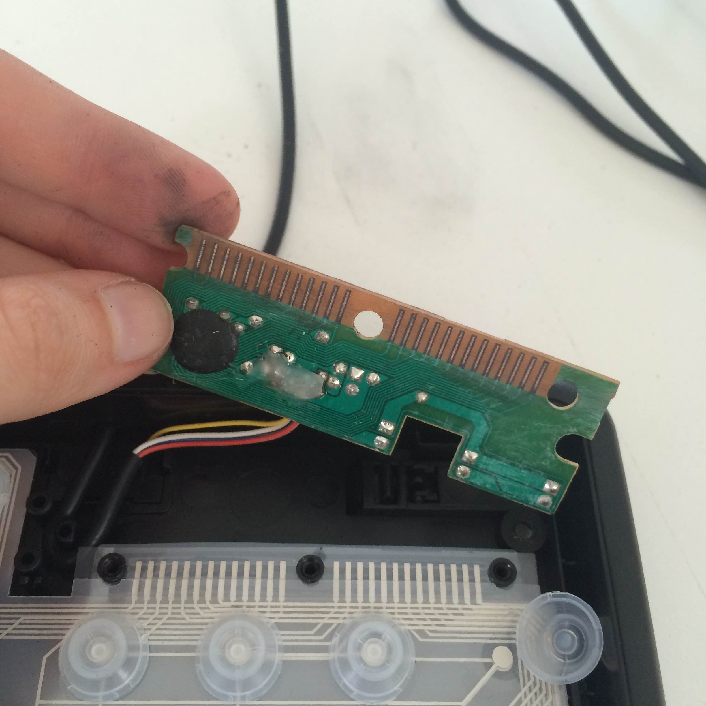
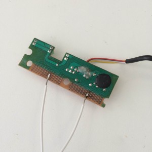
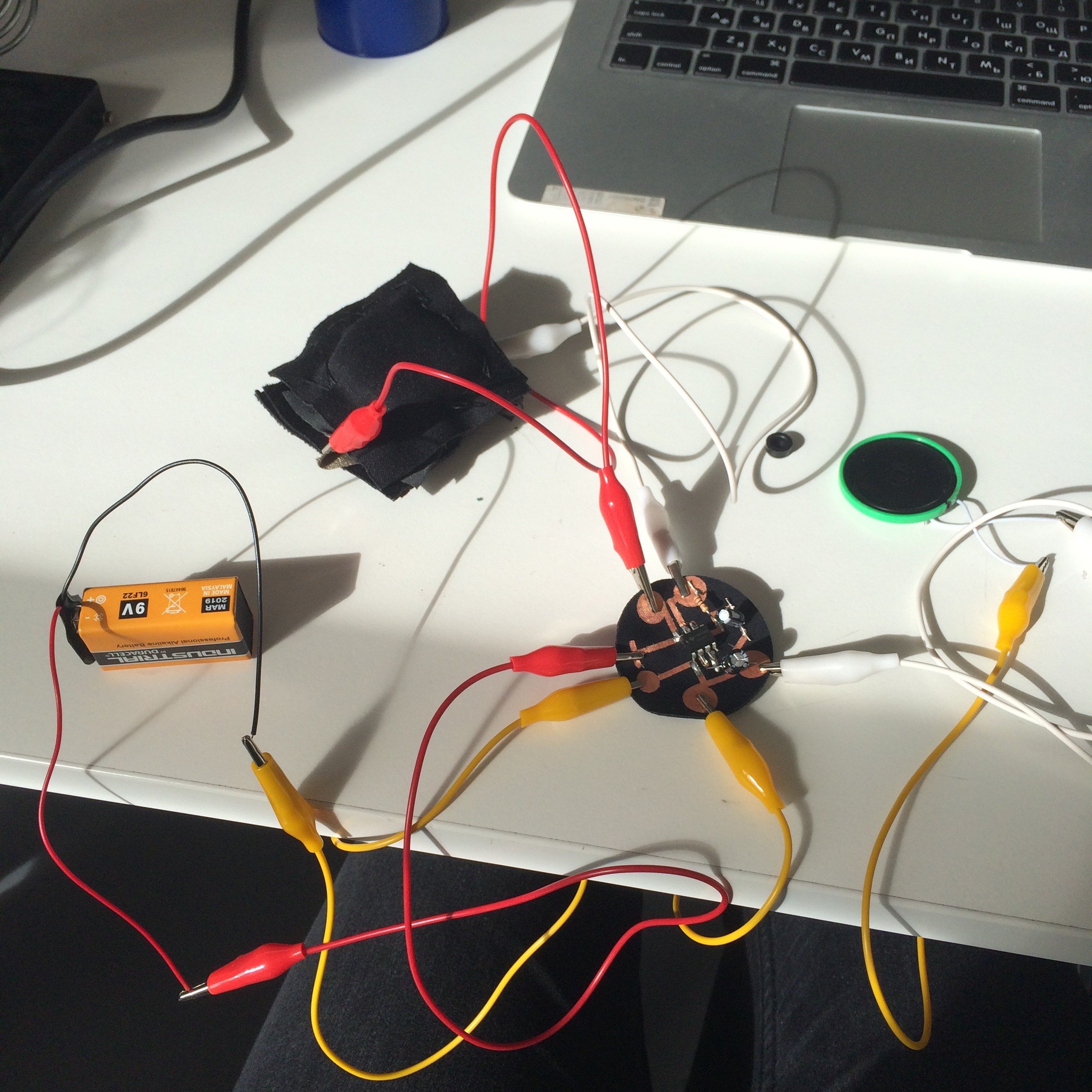
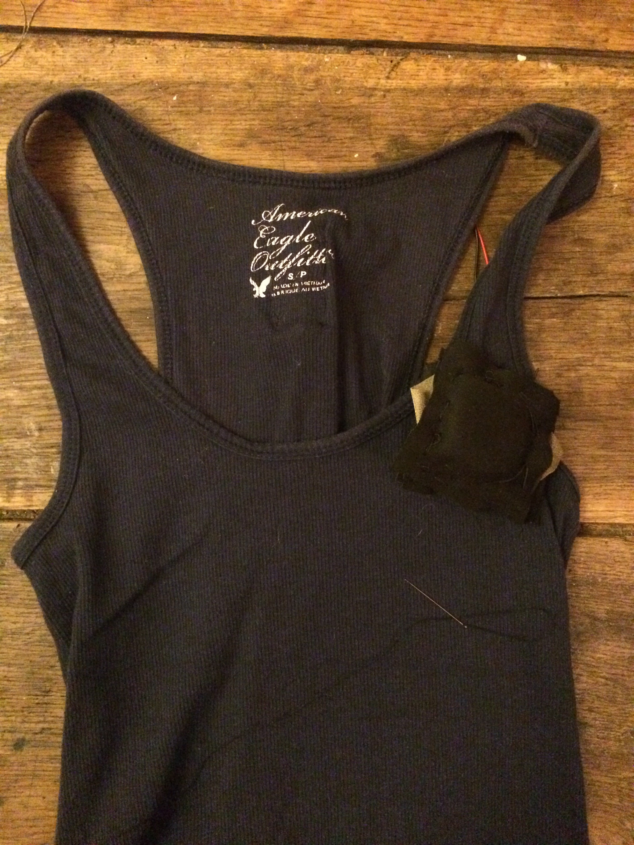
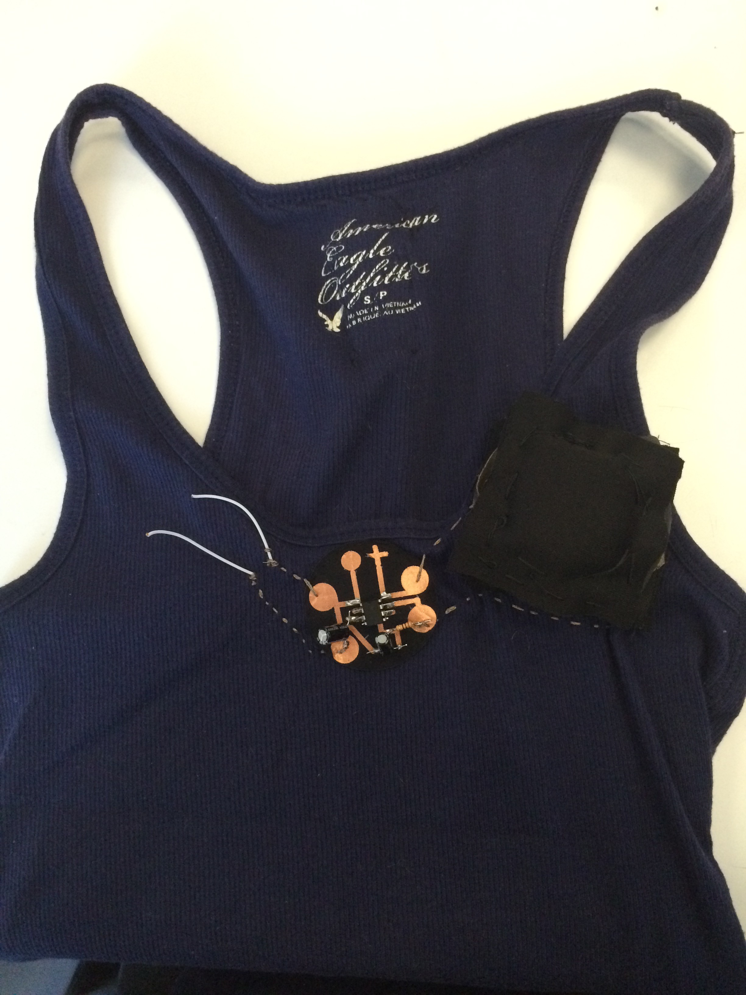
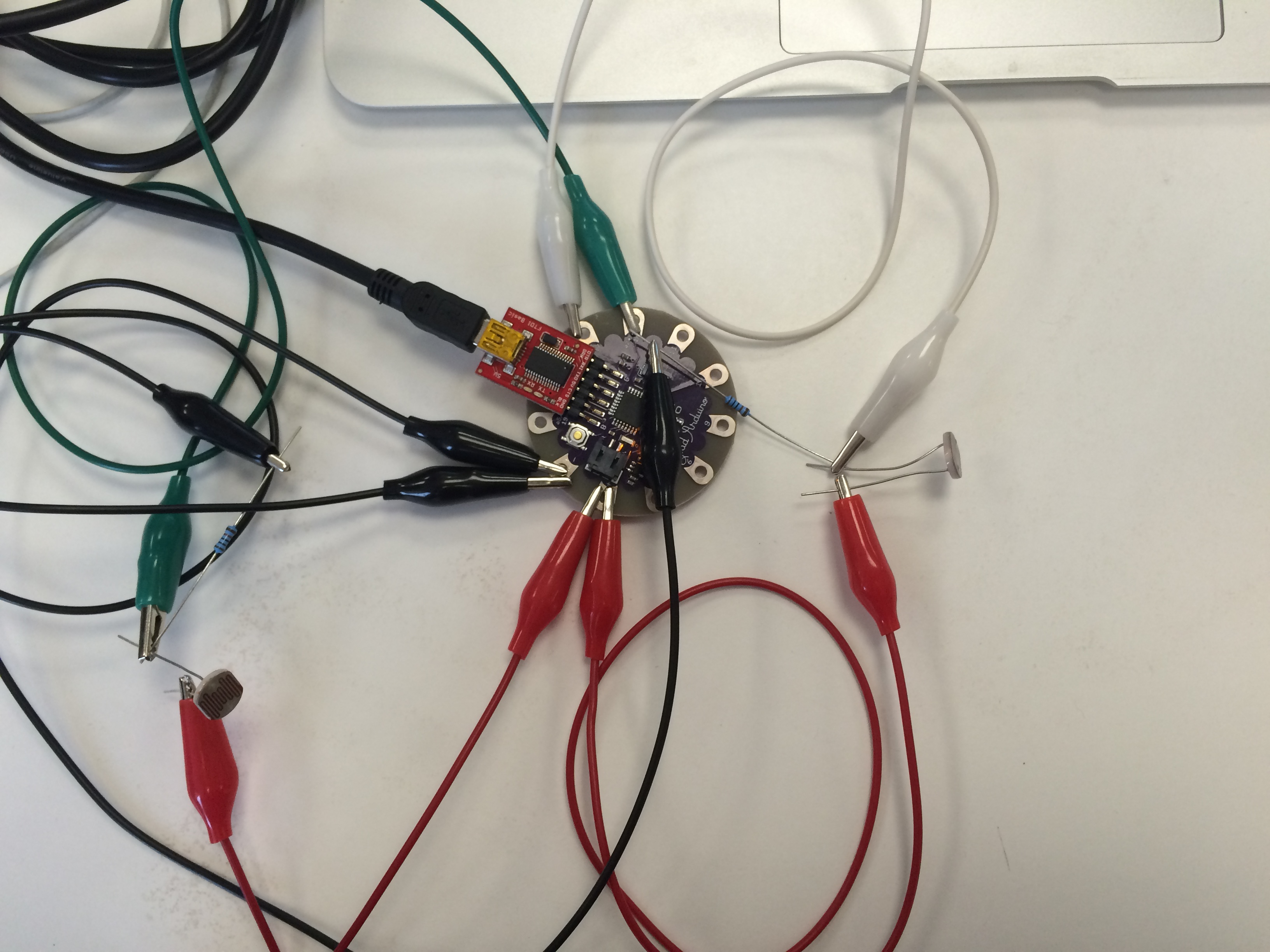
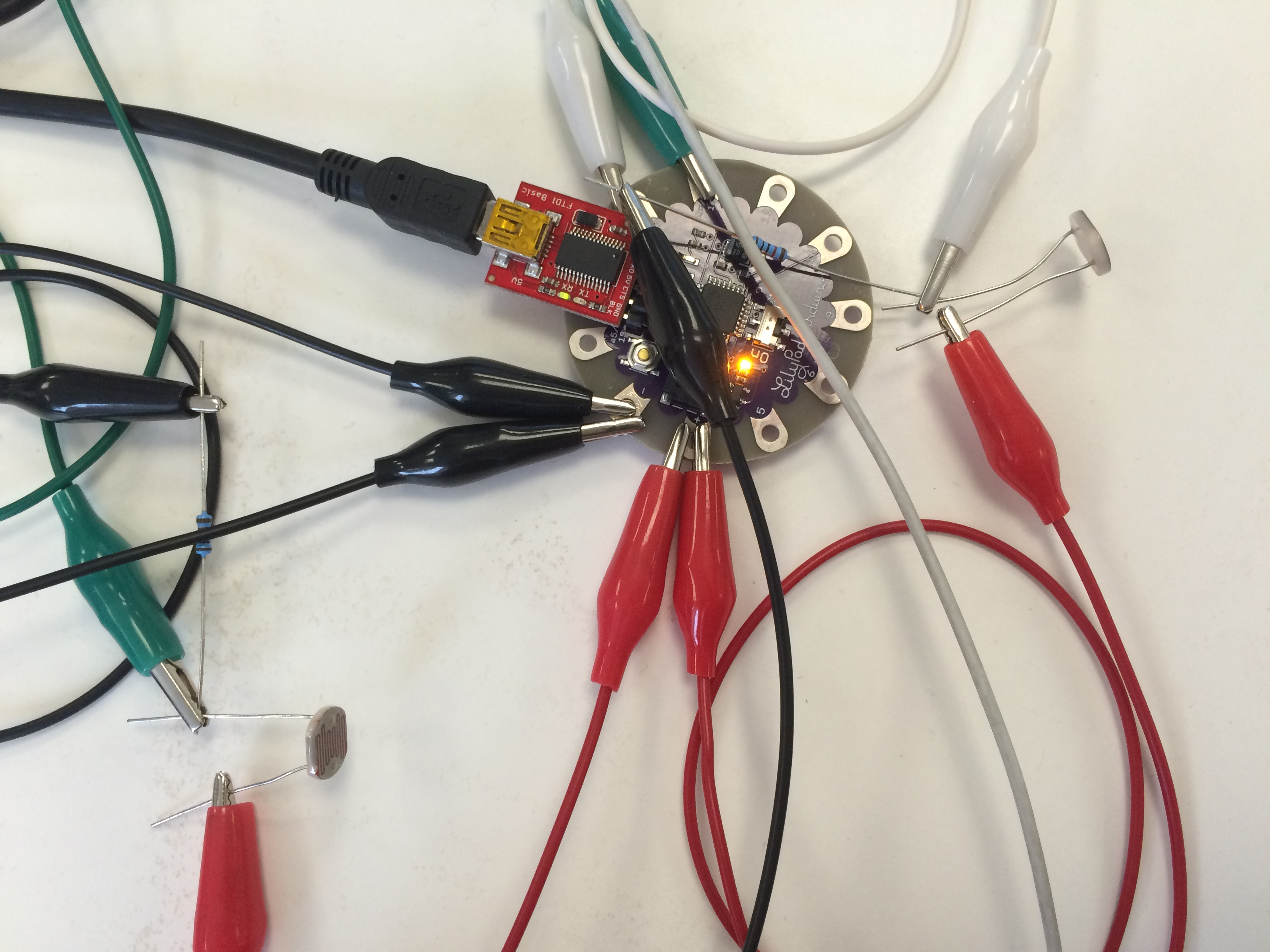
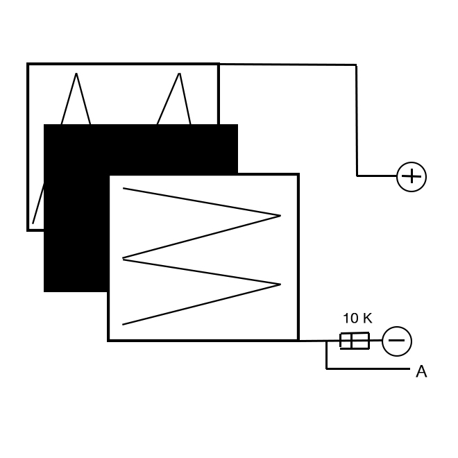
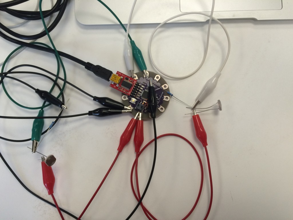
For this flip flop project I started with a lilypad and a code that I found online and then modified. The code creates generated hair-like text.

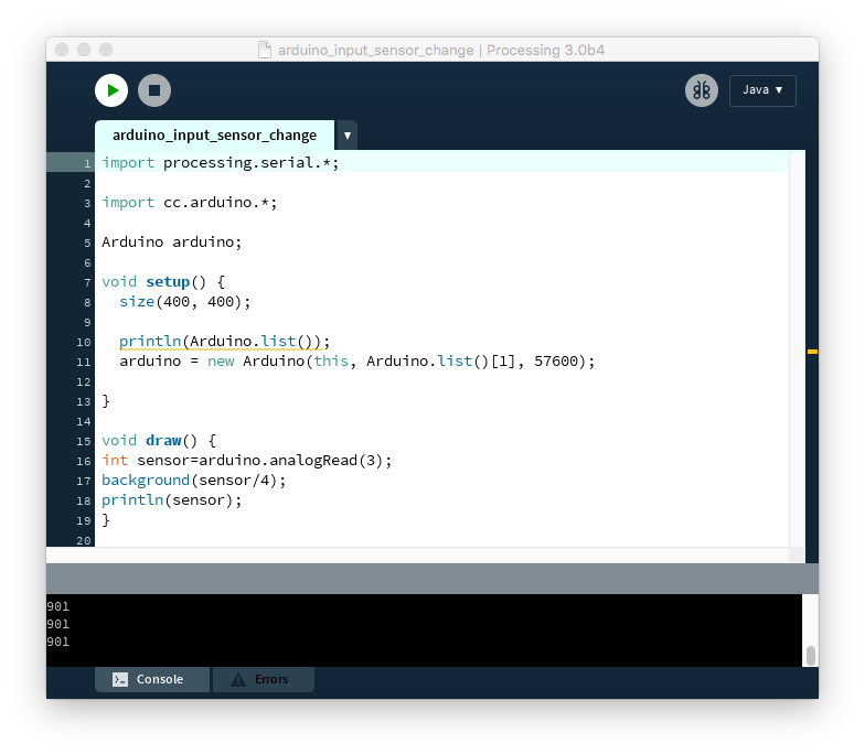
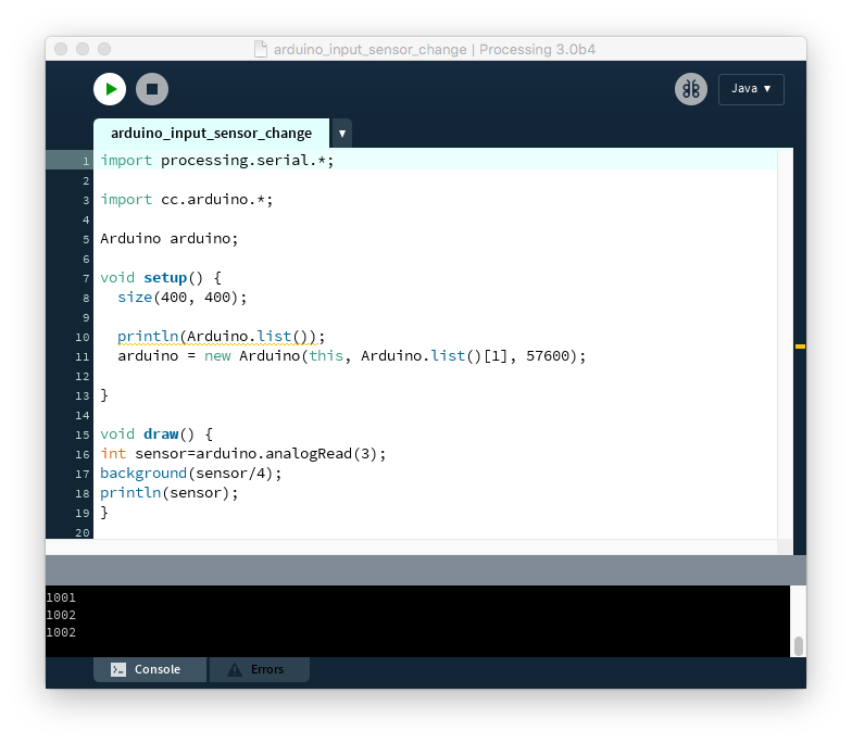
I wanted to use light sensors to control the code. One light sensor would restart the generative text, going through 4 different versions of movement and 4 different colors, the other sensor would change the colors by making them lighter or darker depending on the light value.

IMG_6412 IMG_6415

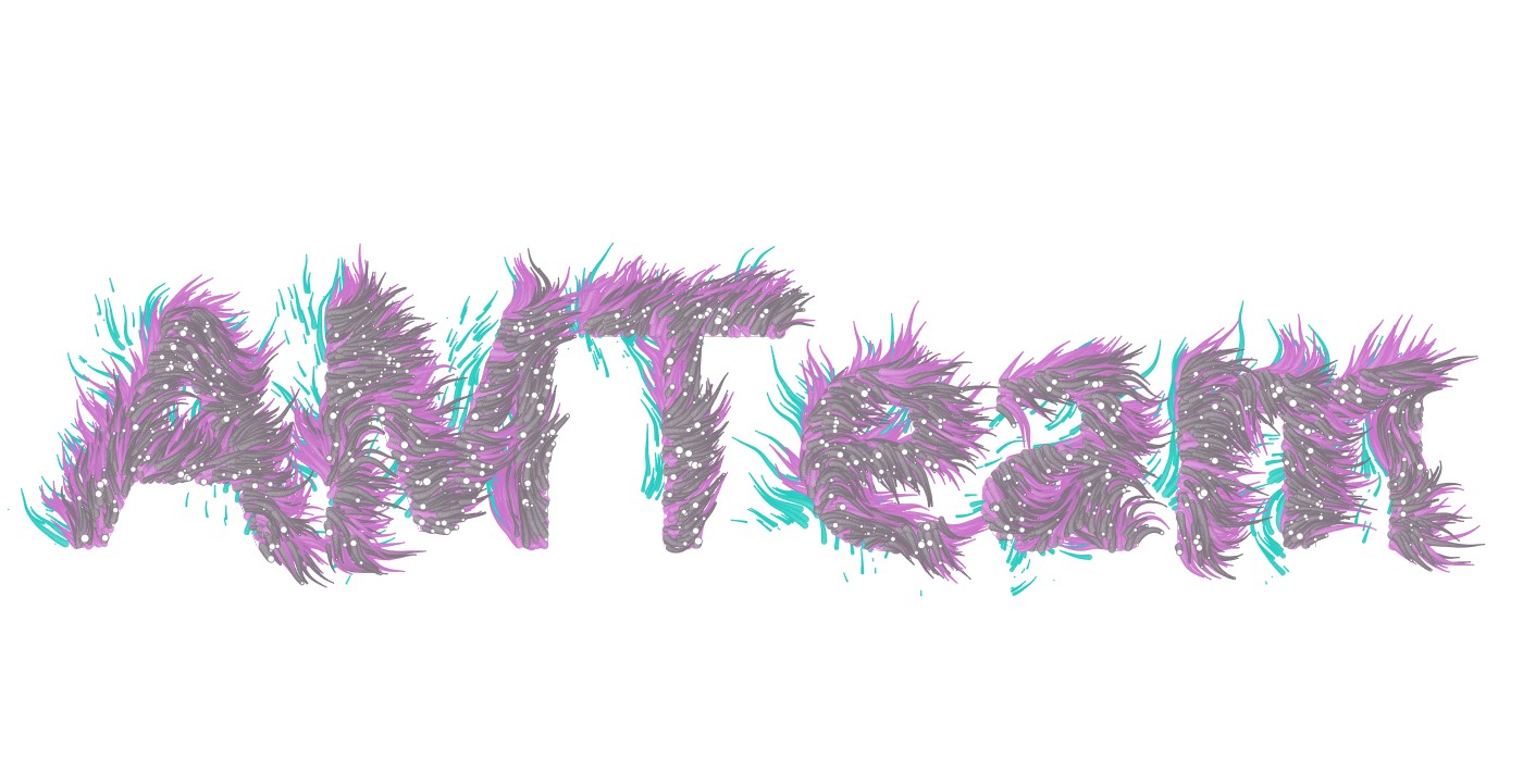
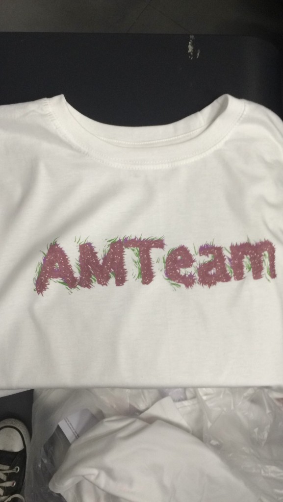
These are the kind of graphics that I ended up with and I created 12 different ones to then print on T-shirts.

screen0008

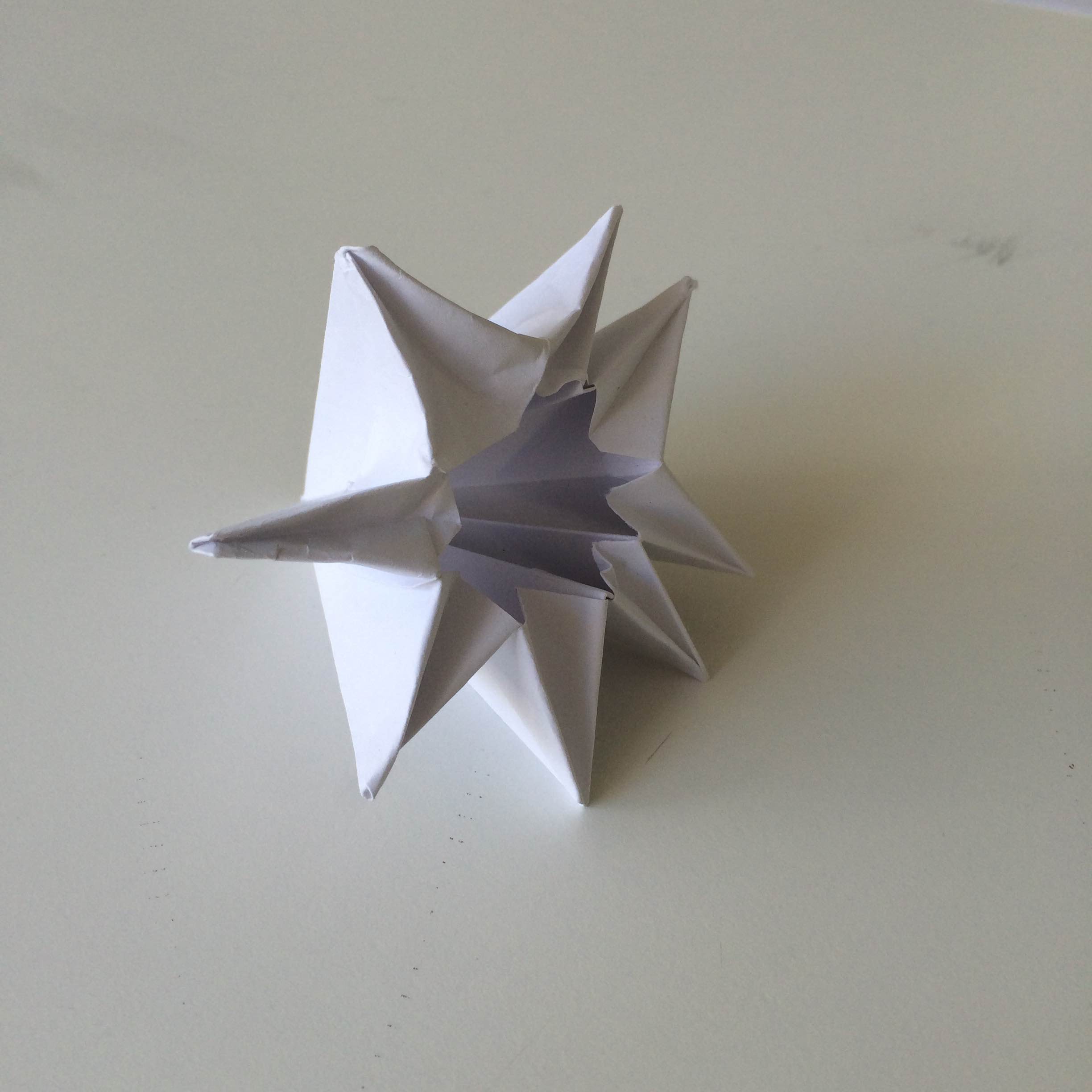
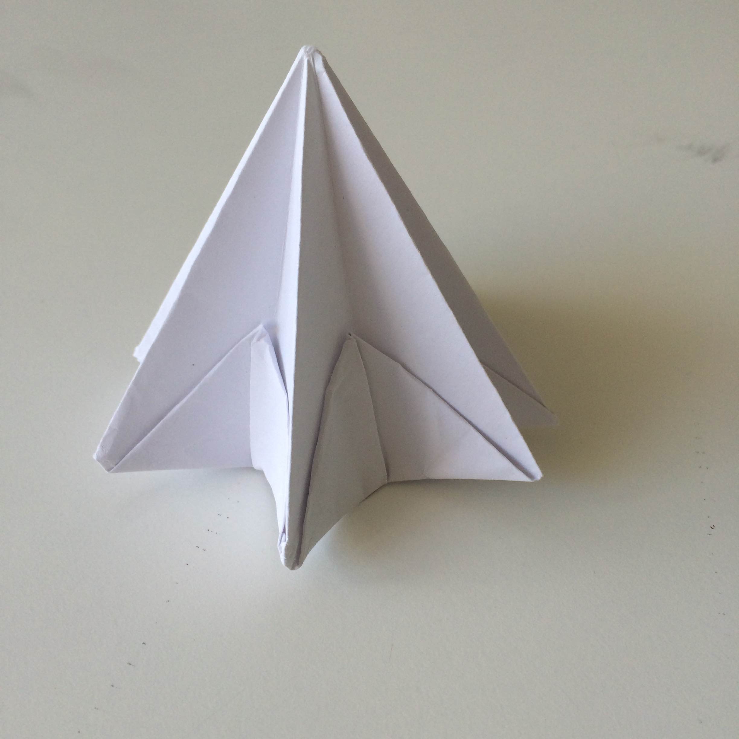
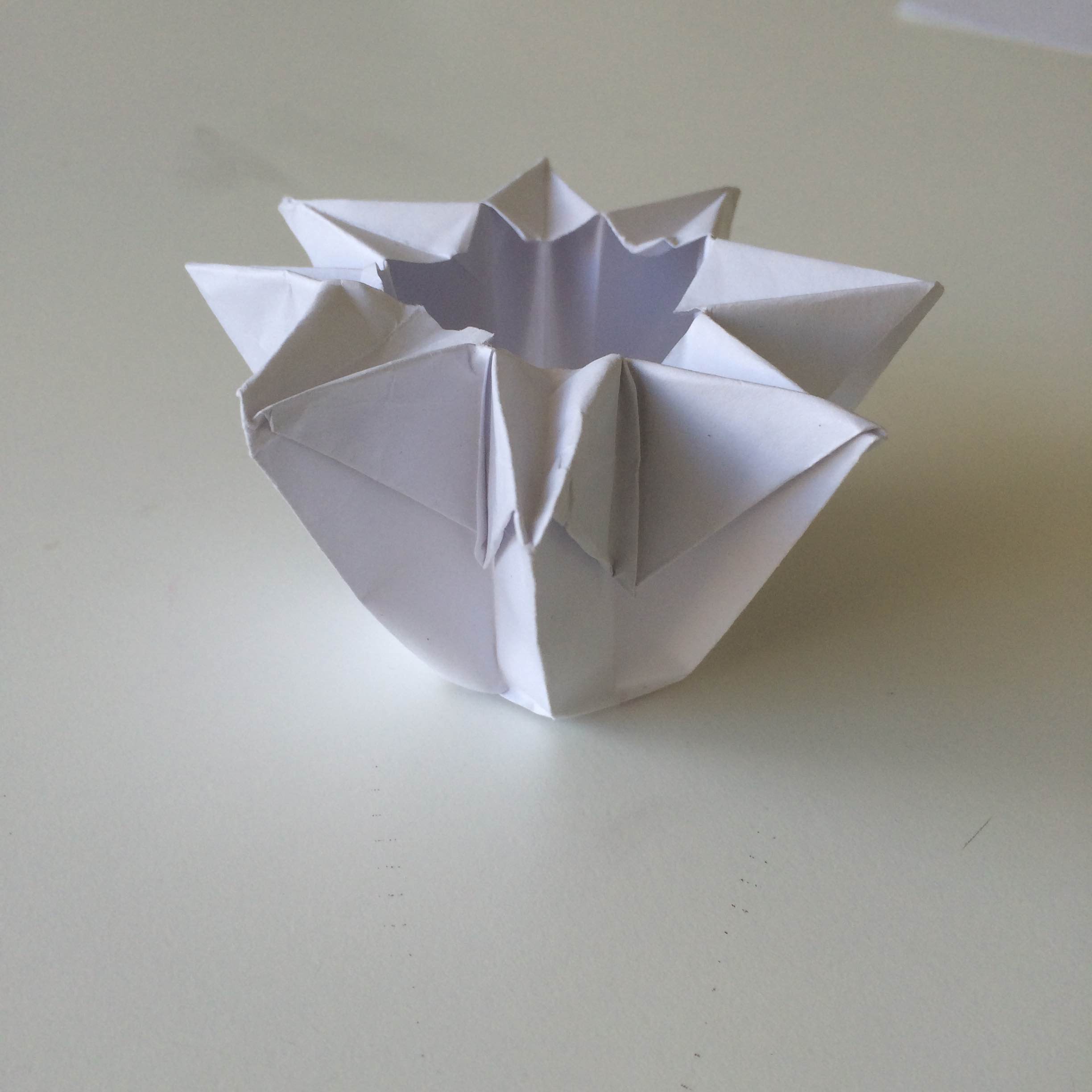
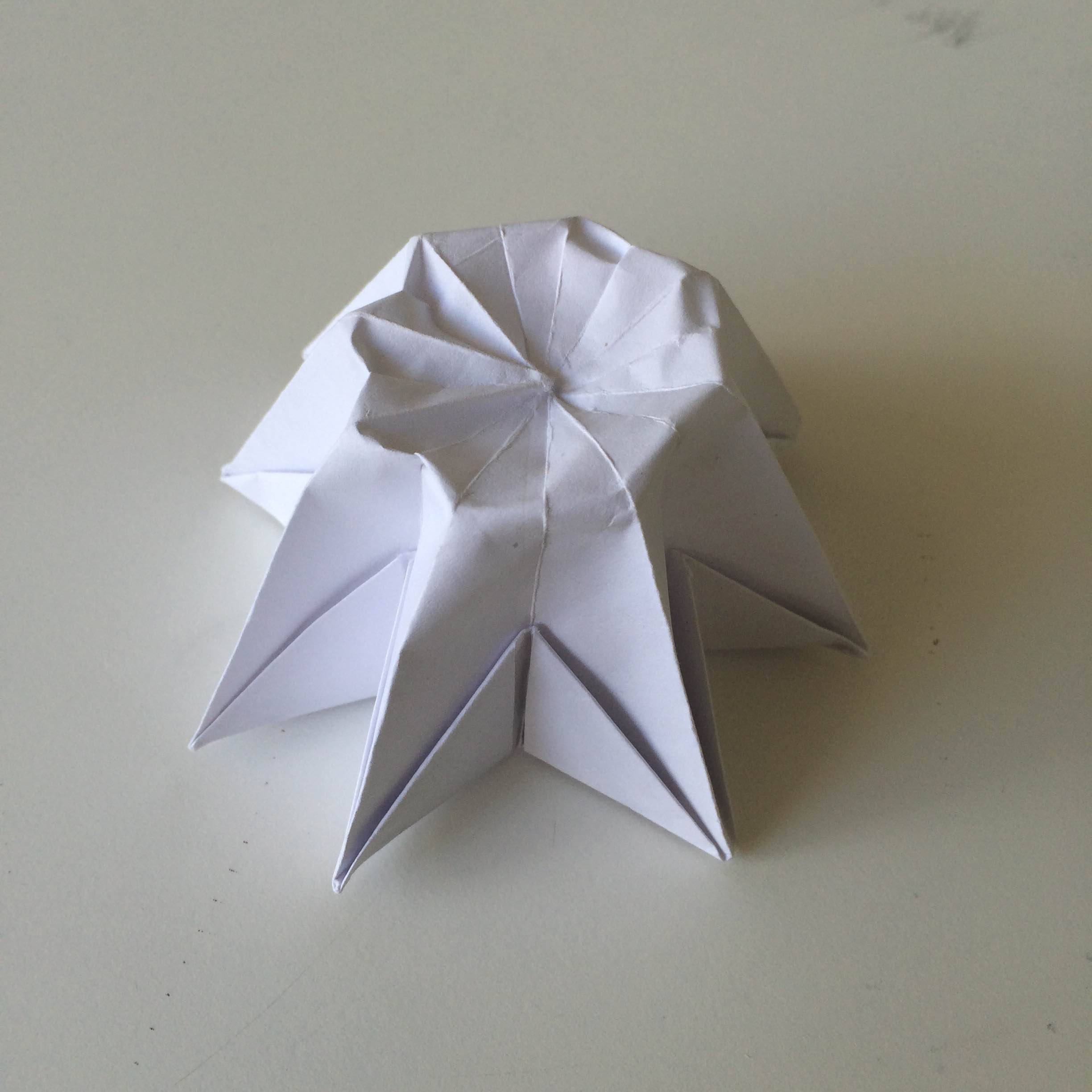
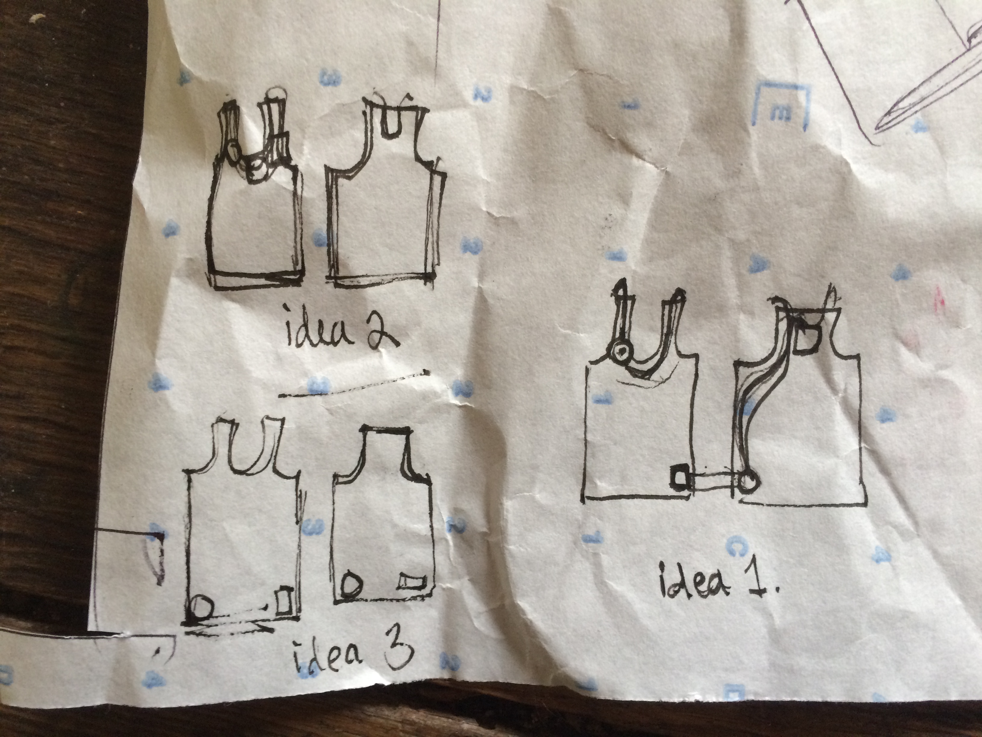
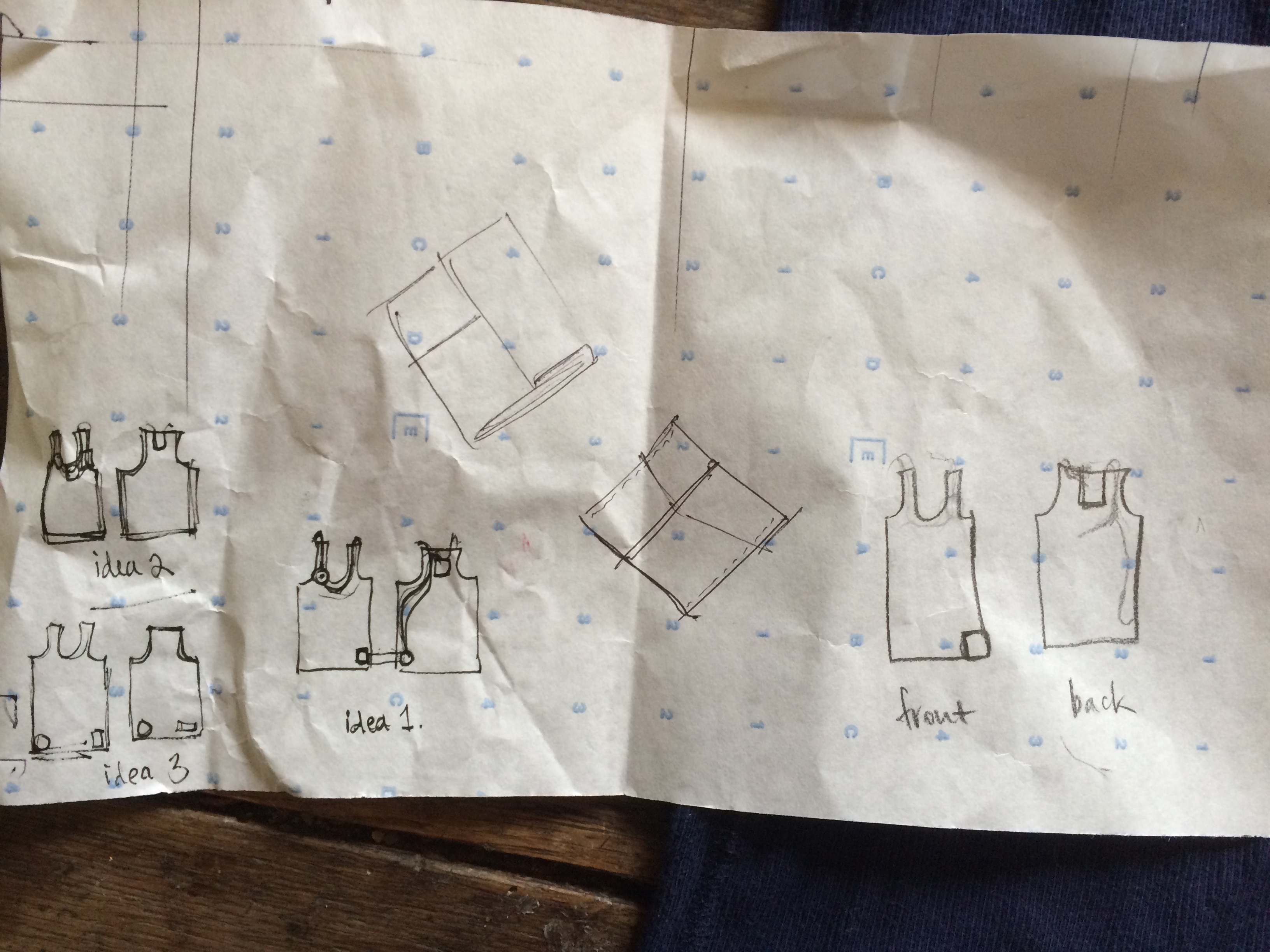
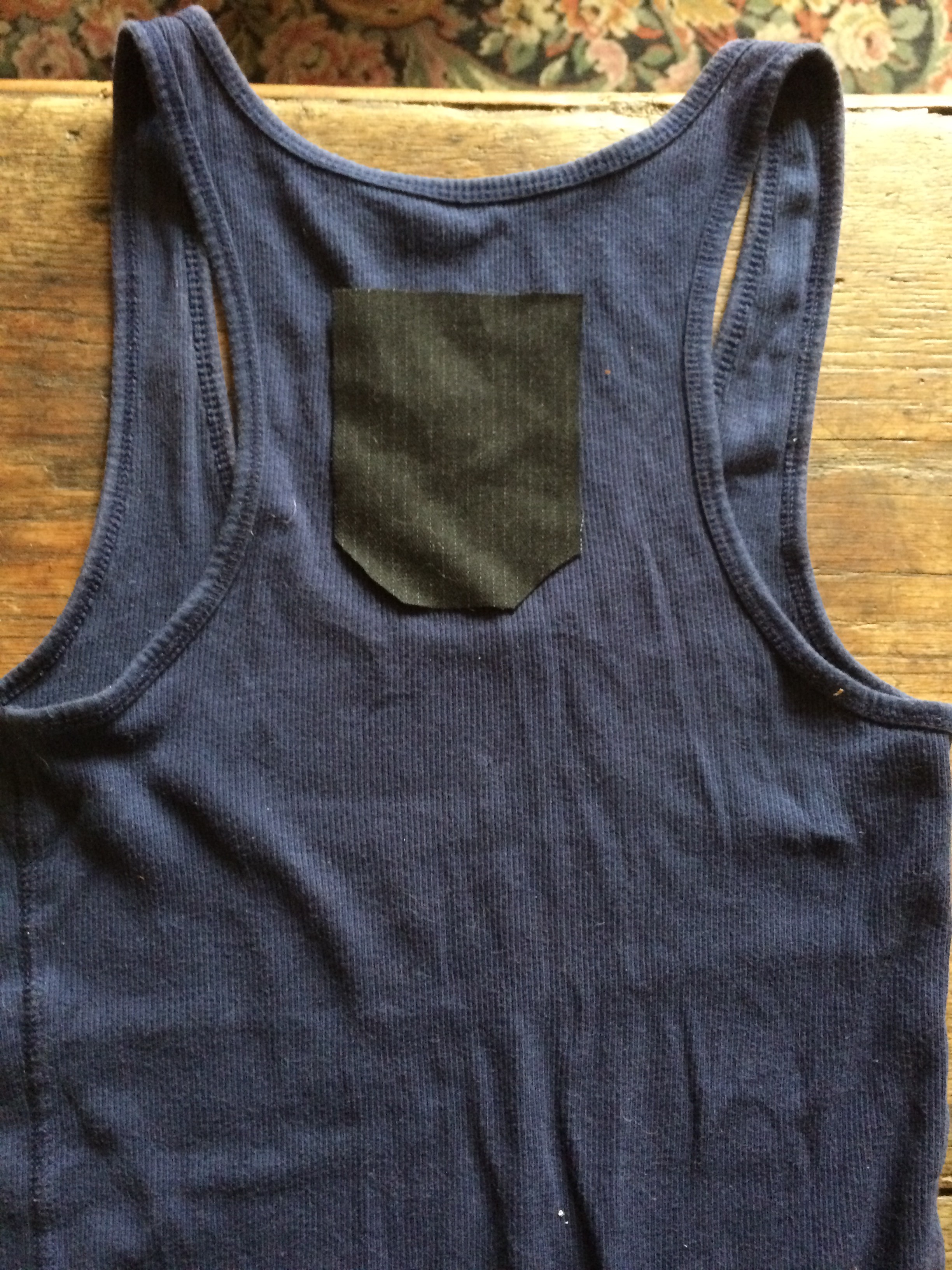
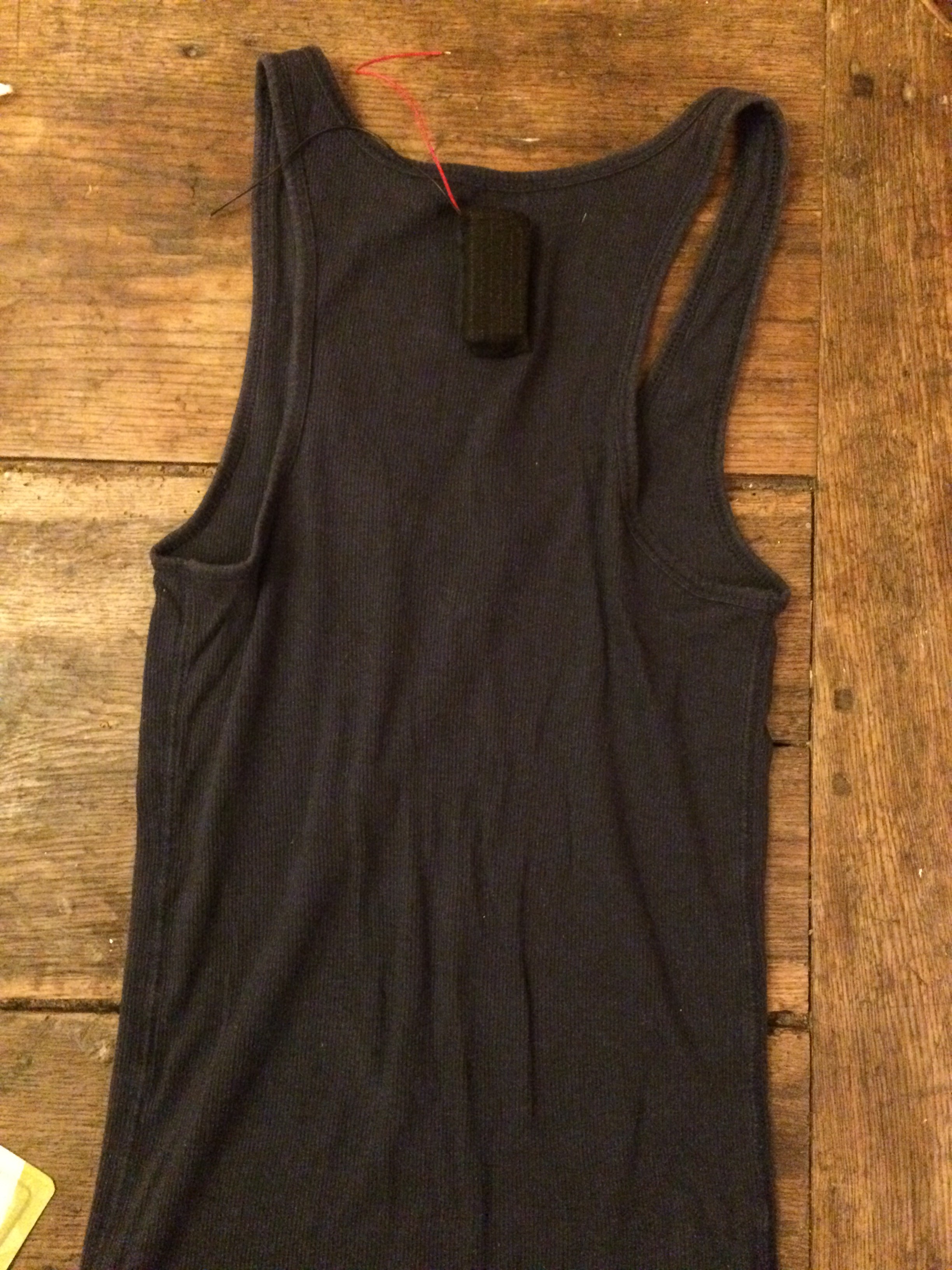
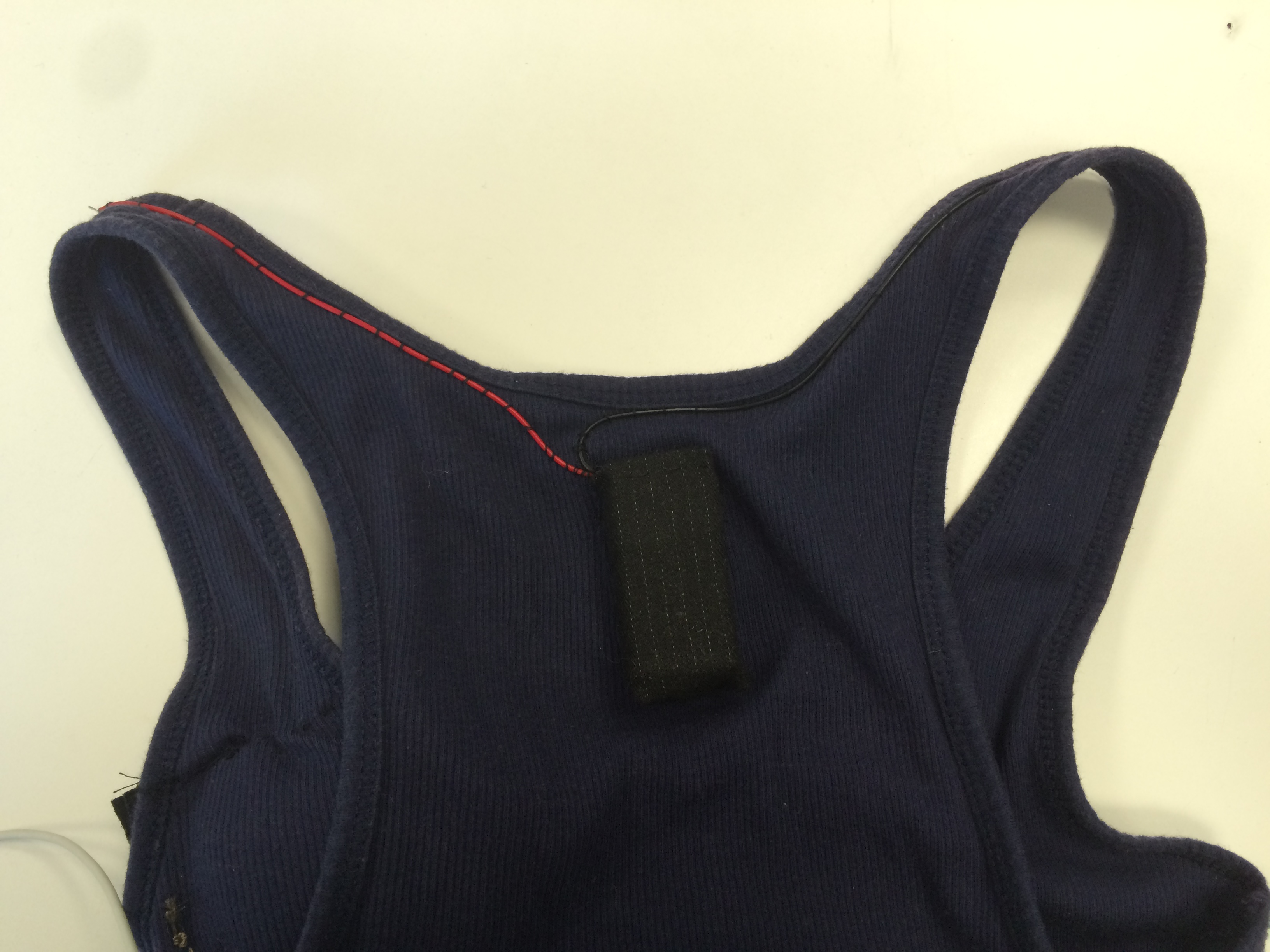
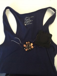
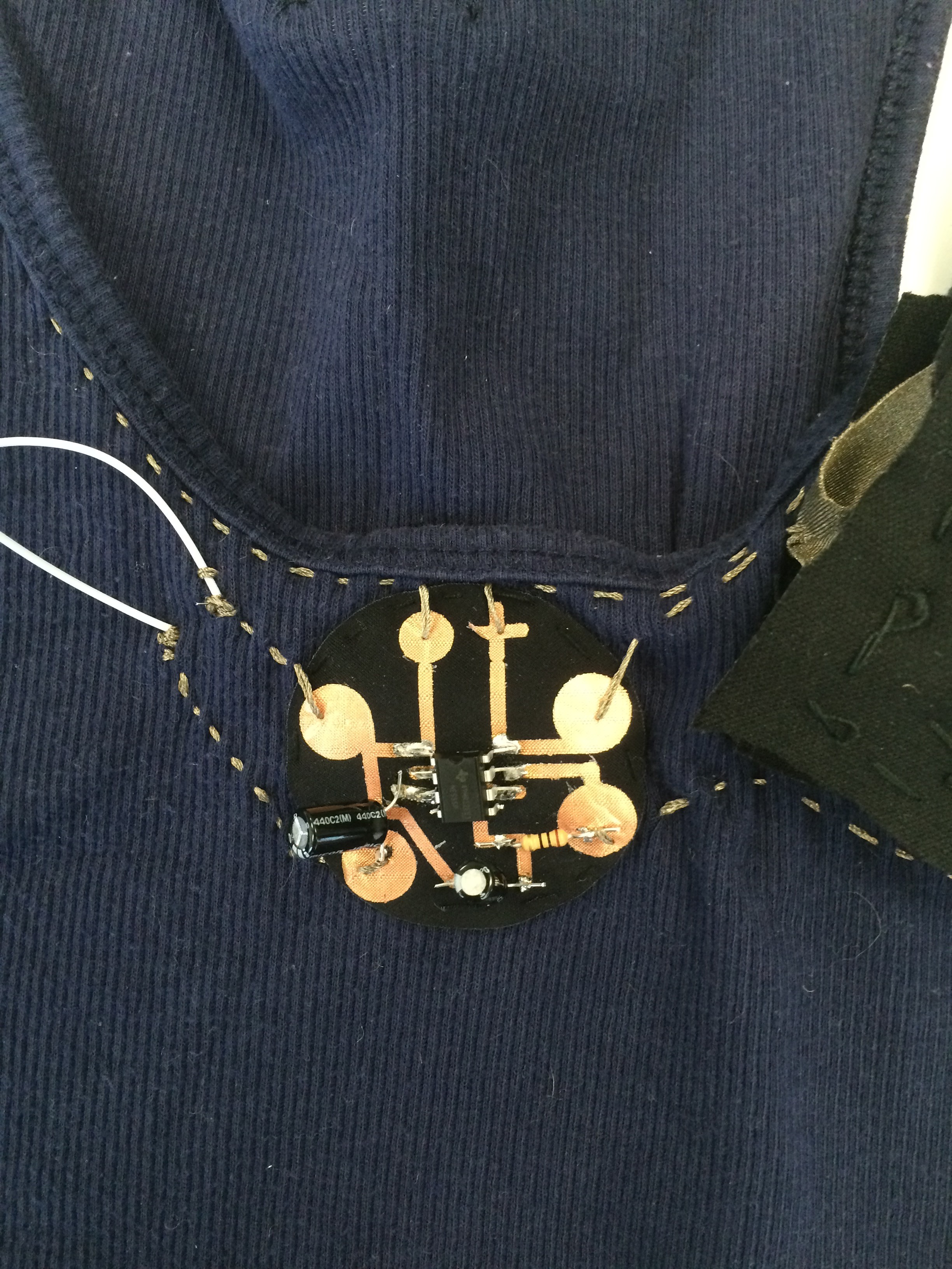
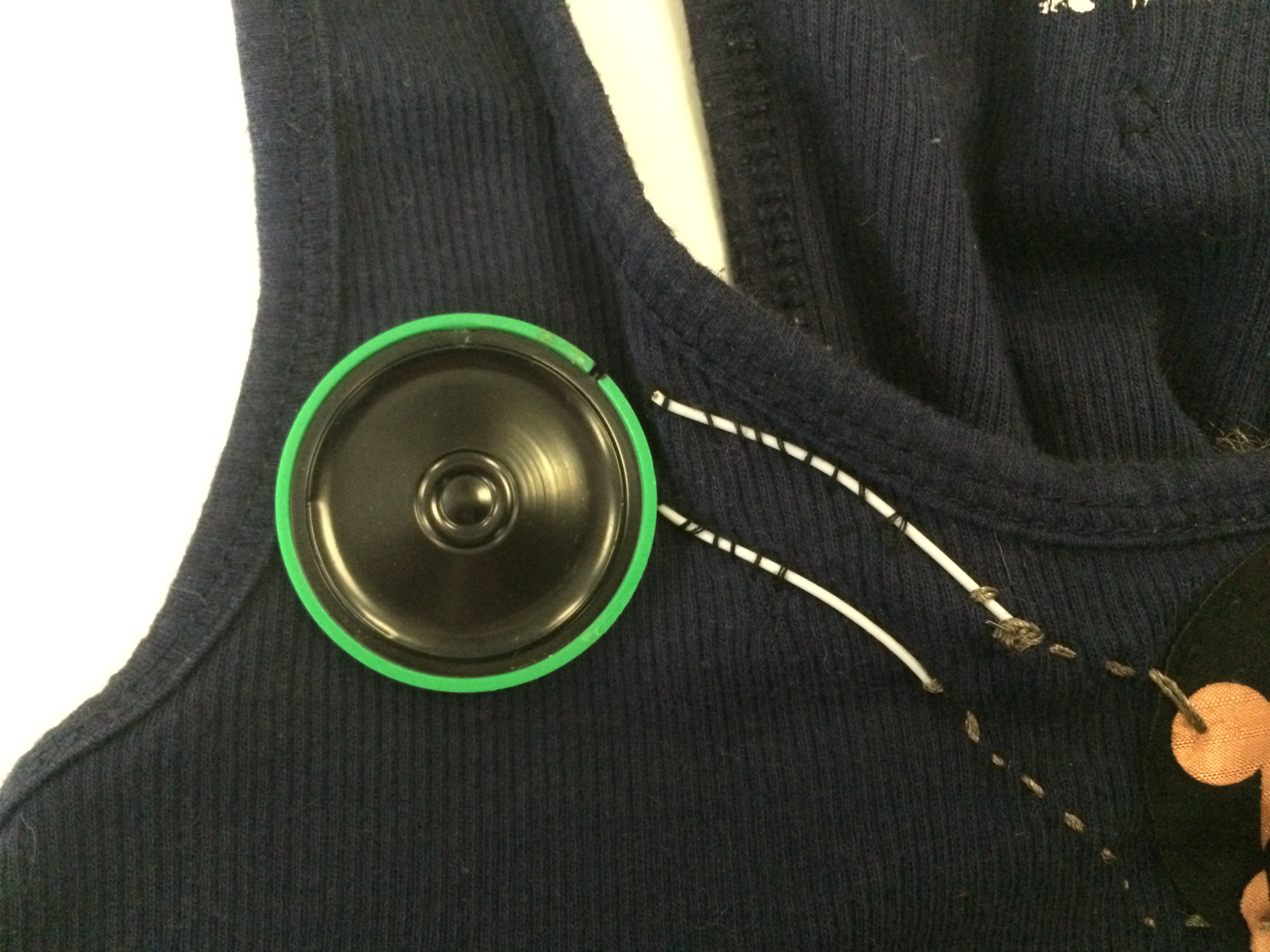
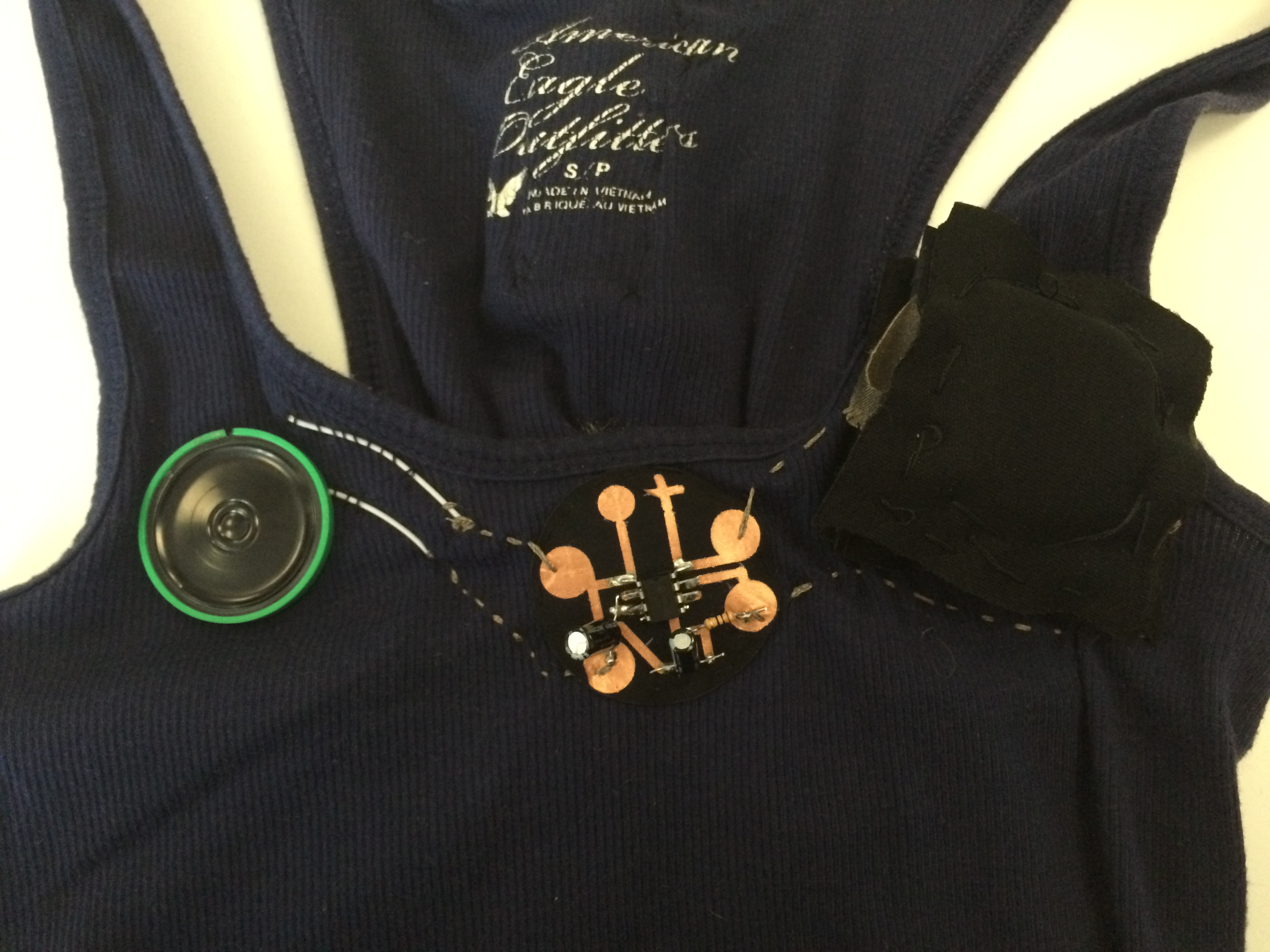
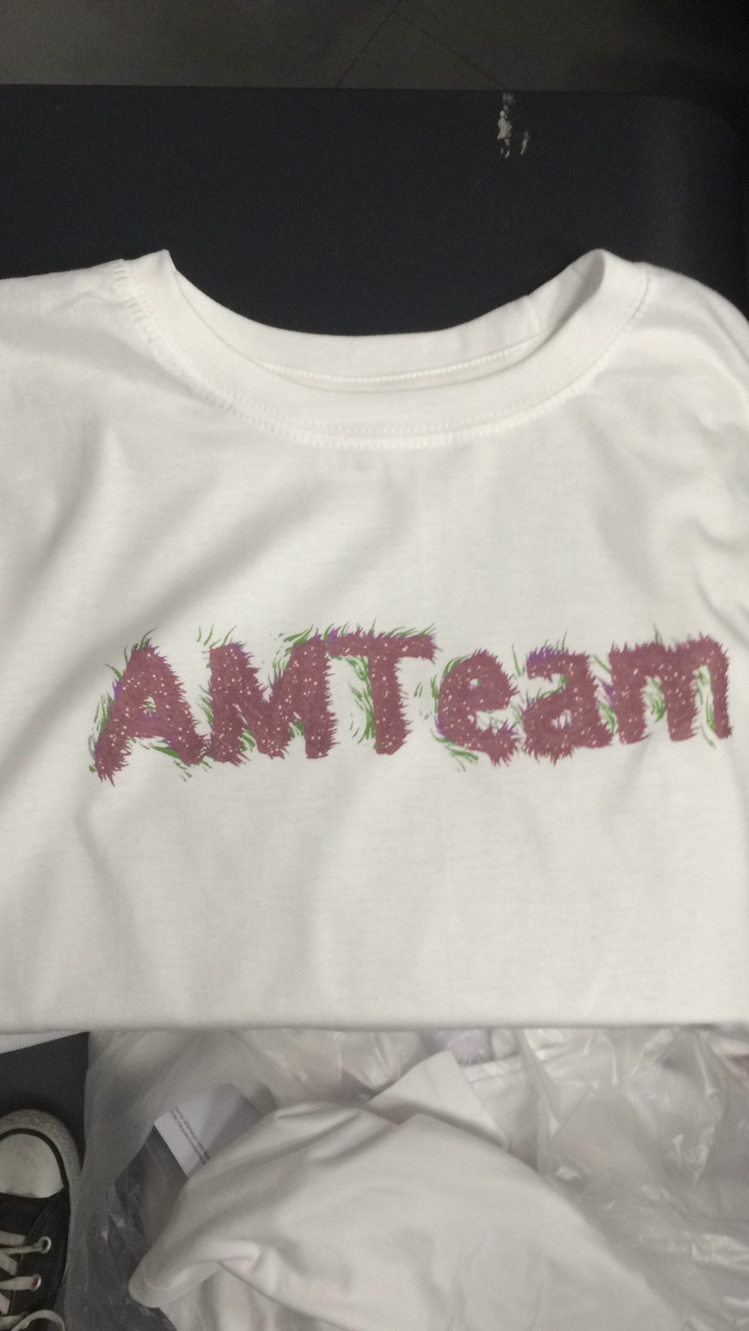
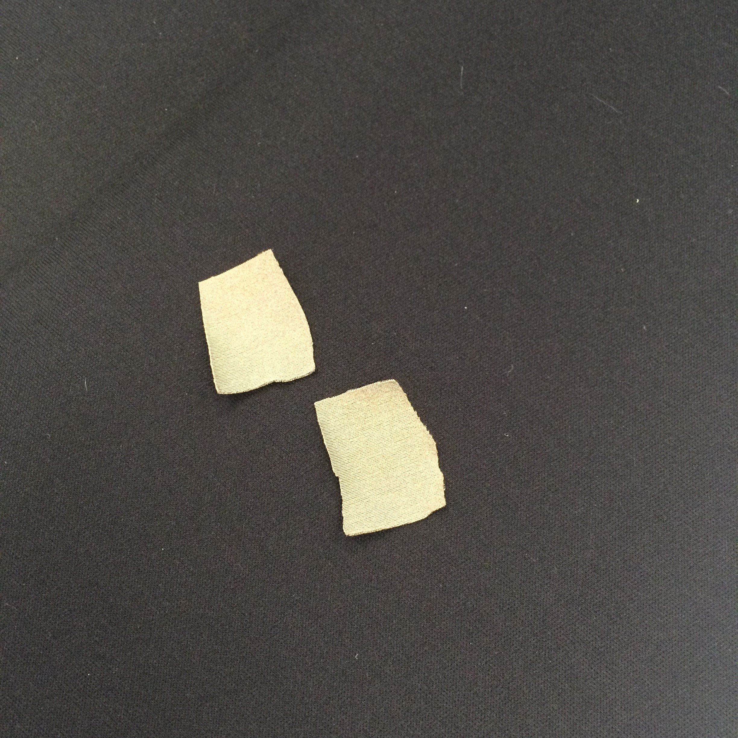
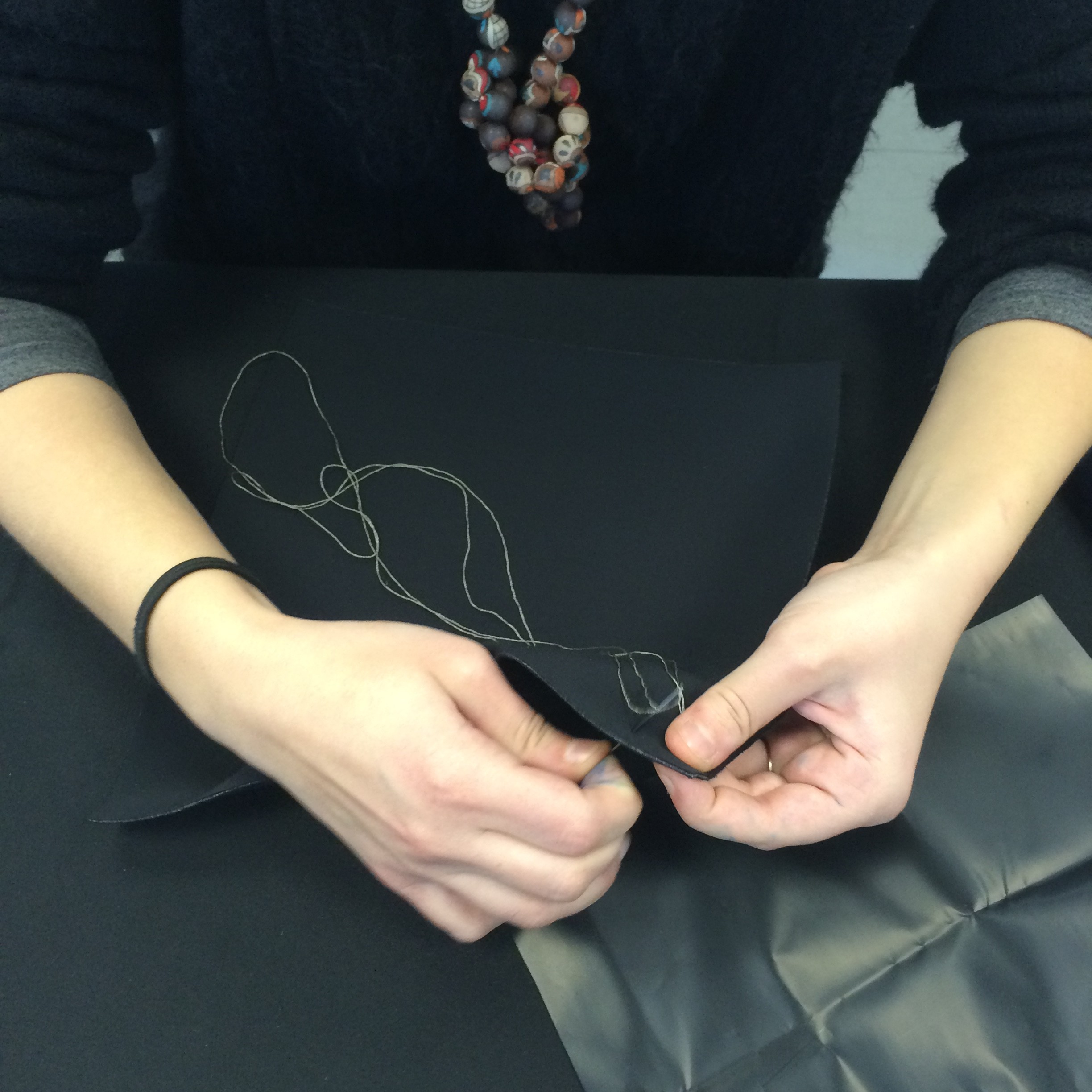
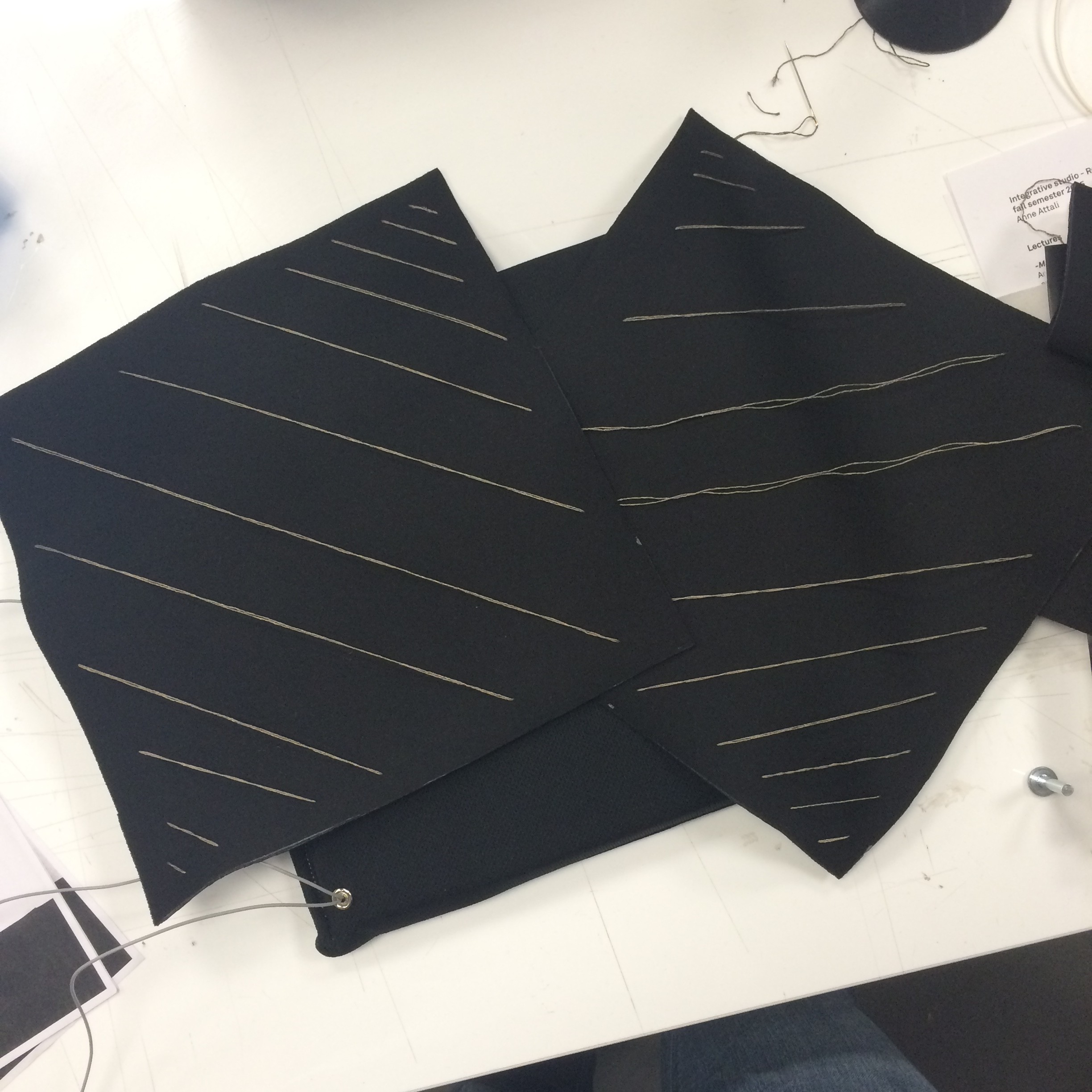
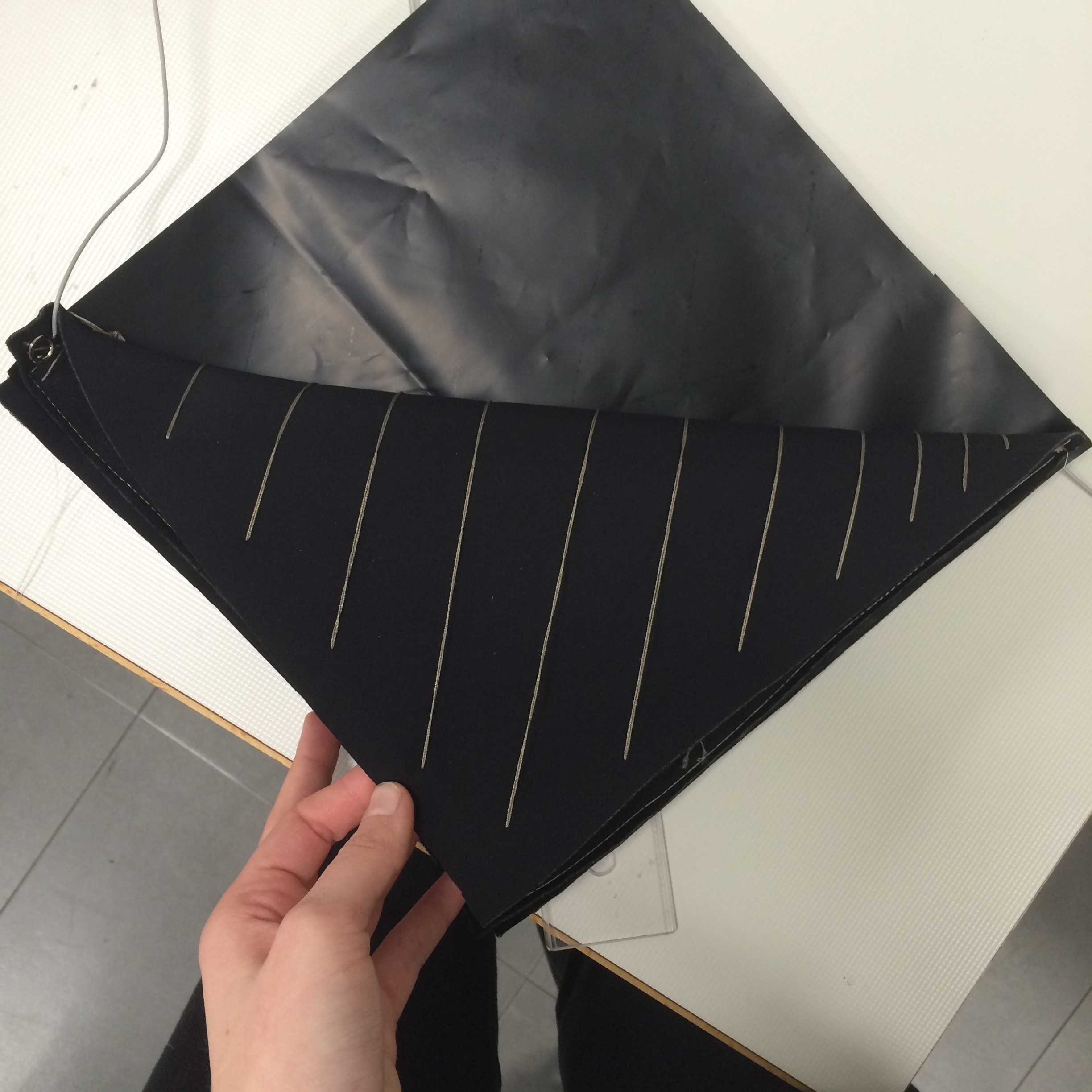
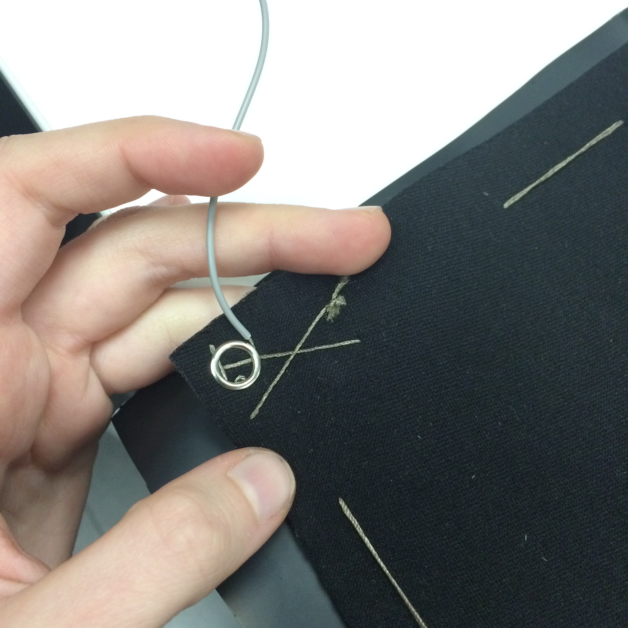
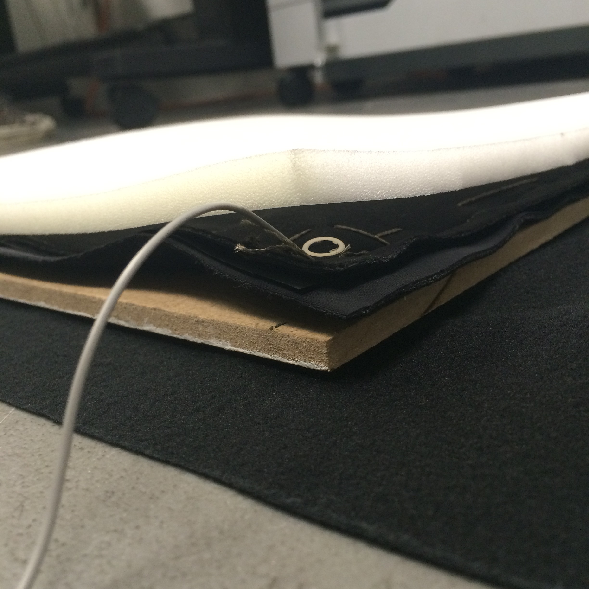
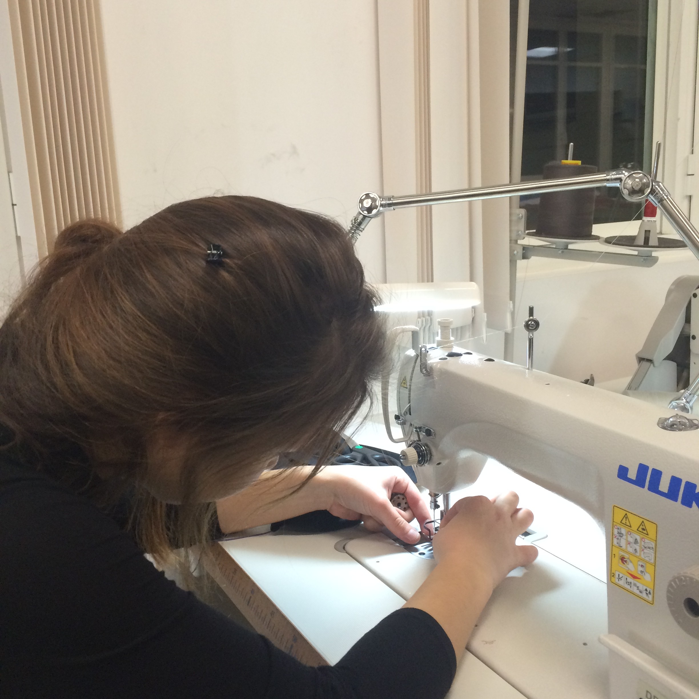
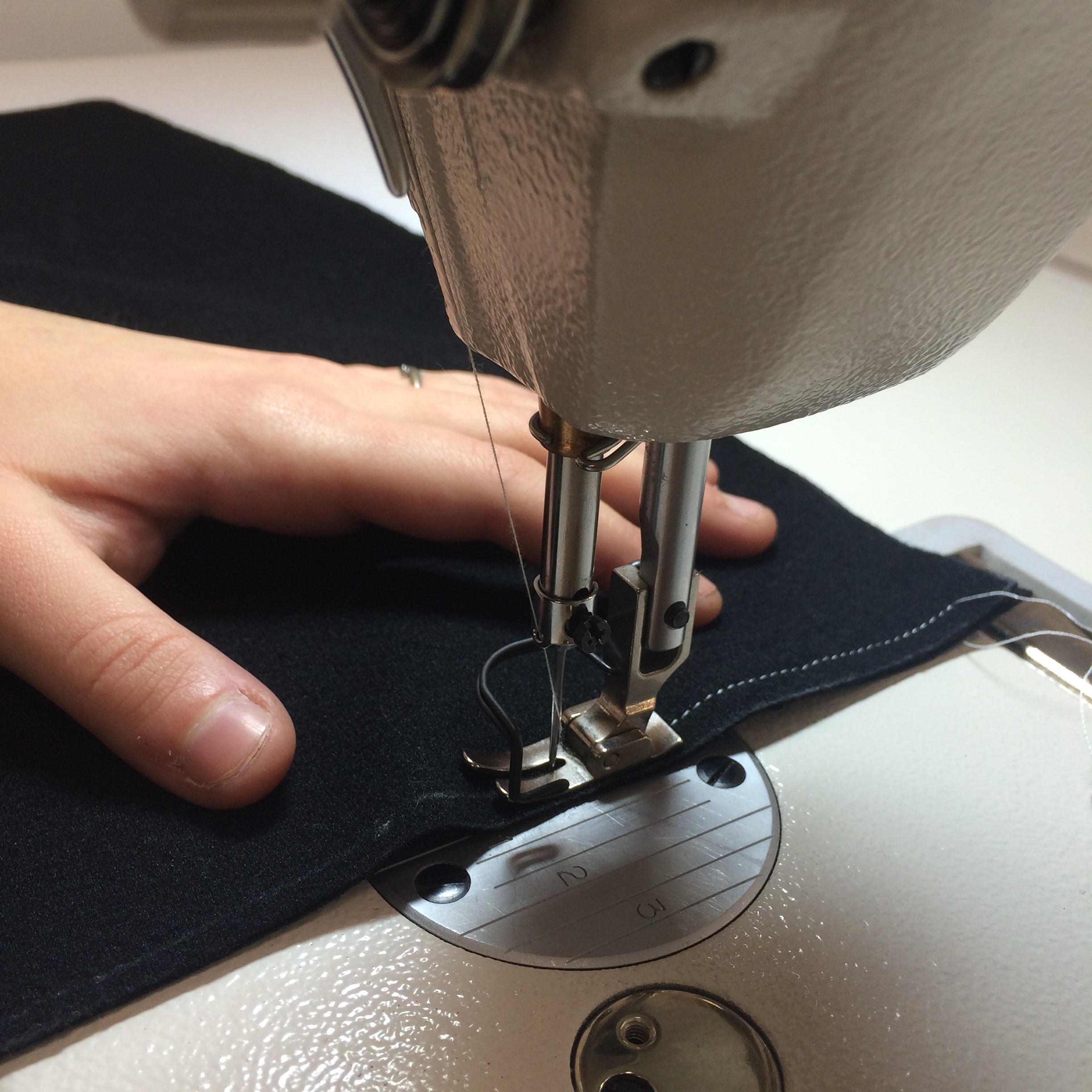
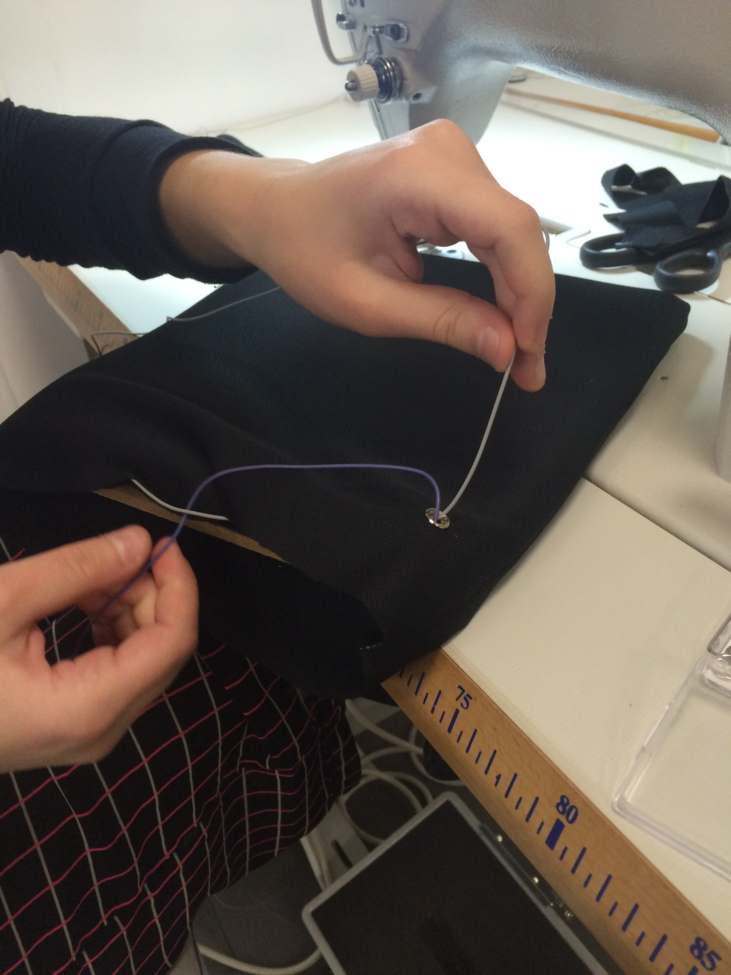
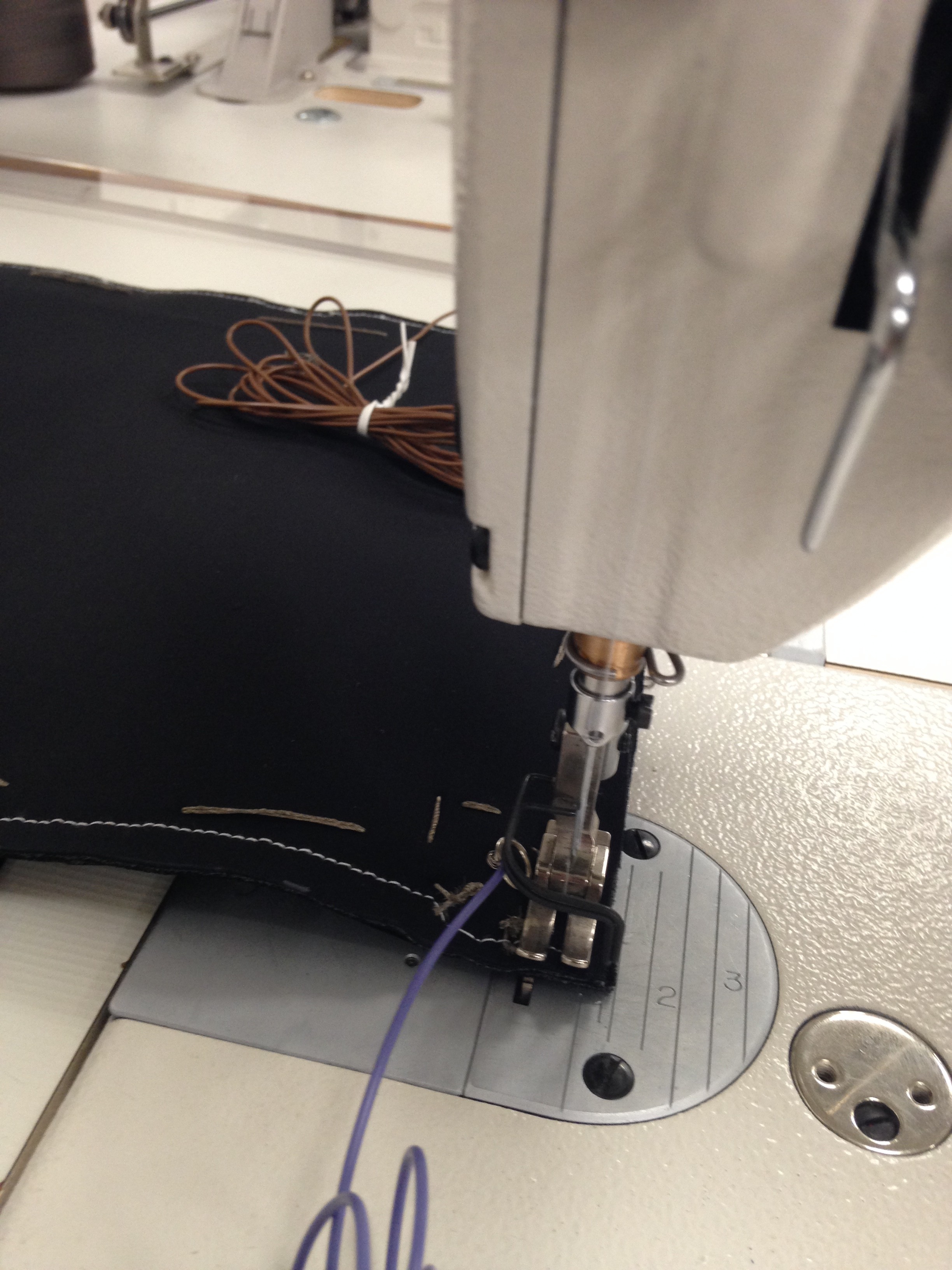
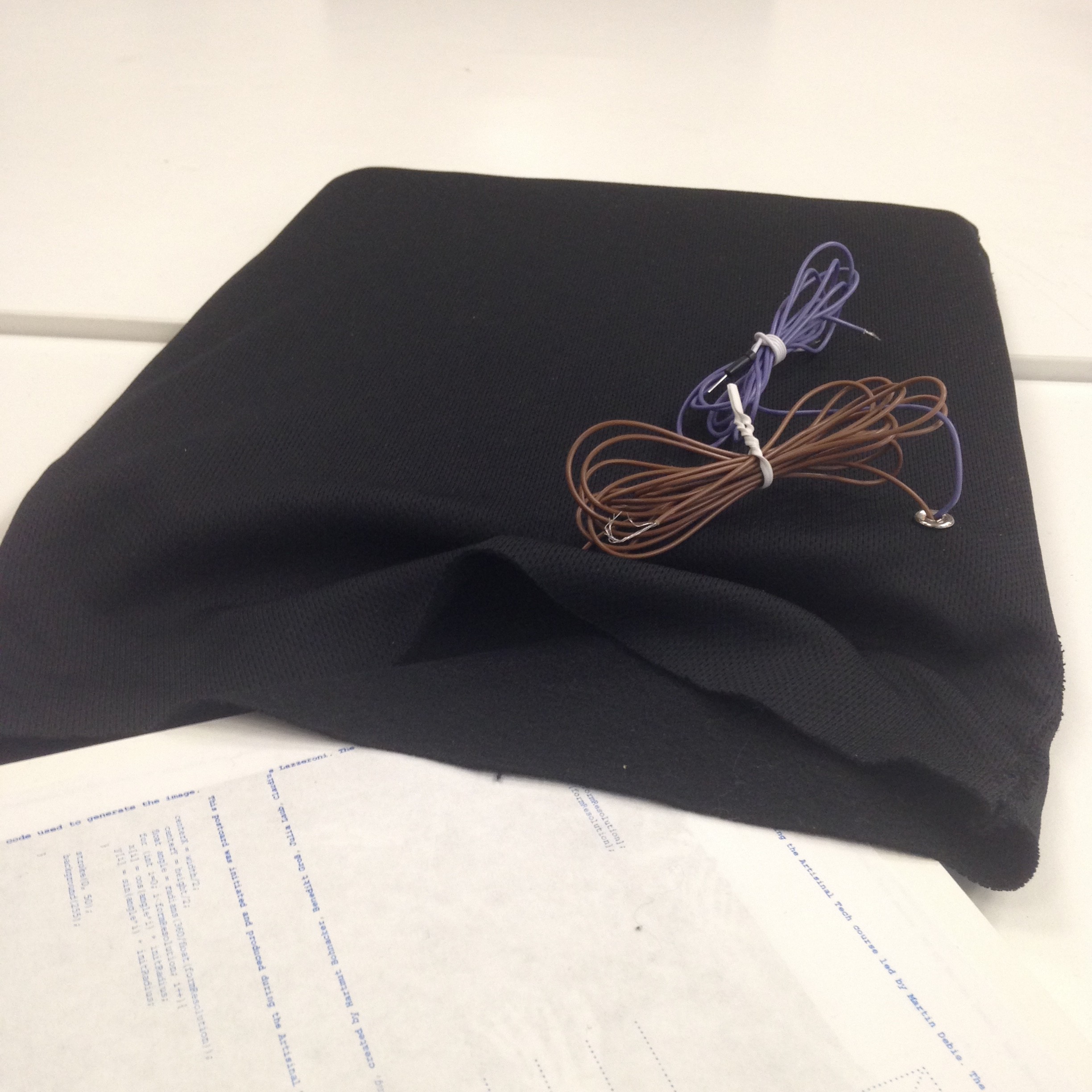
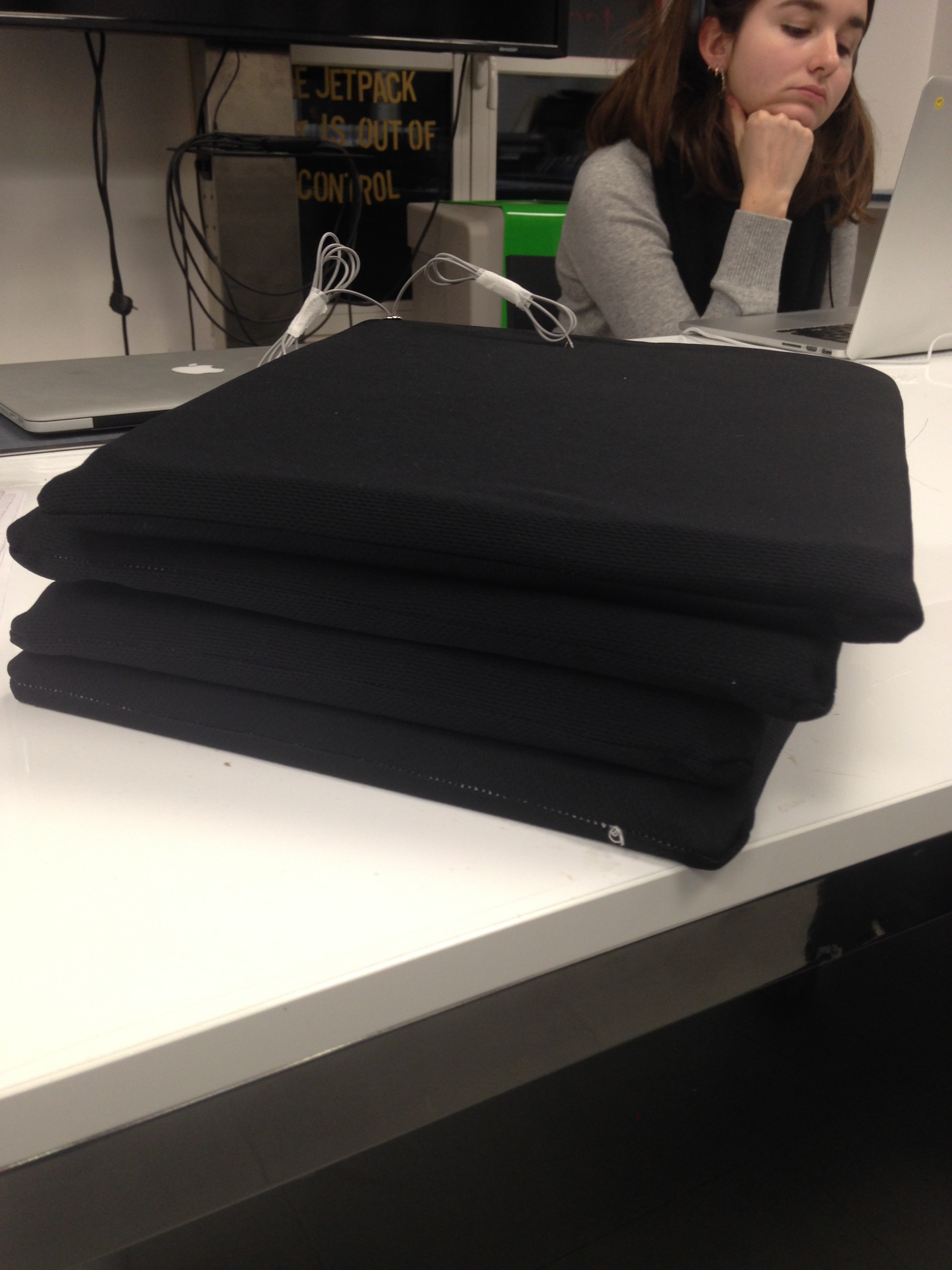
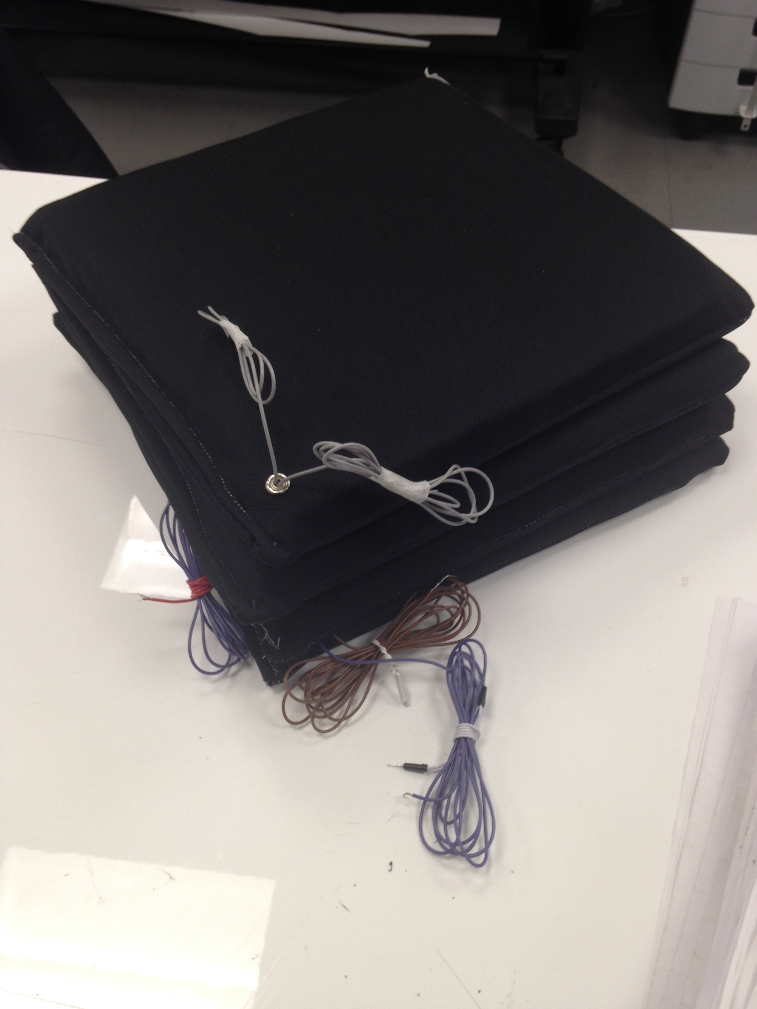
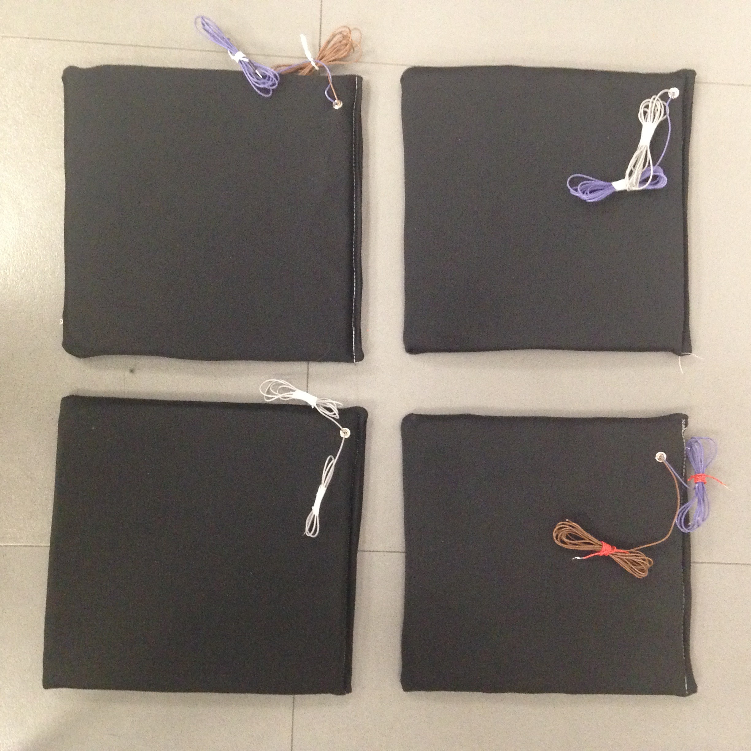
Here are some of the process pictures of the shirts after printing:
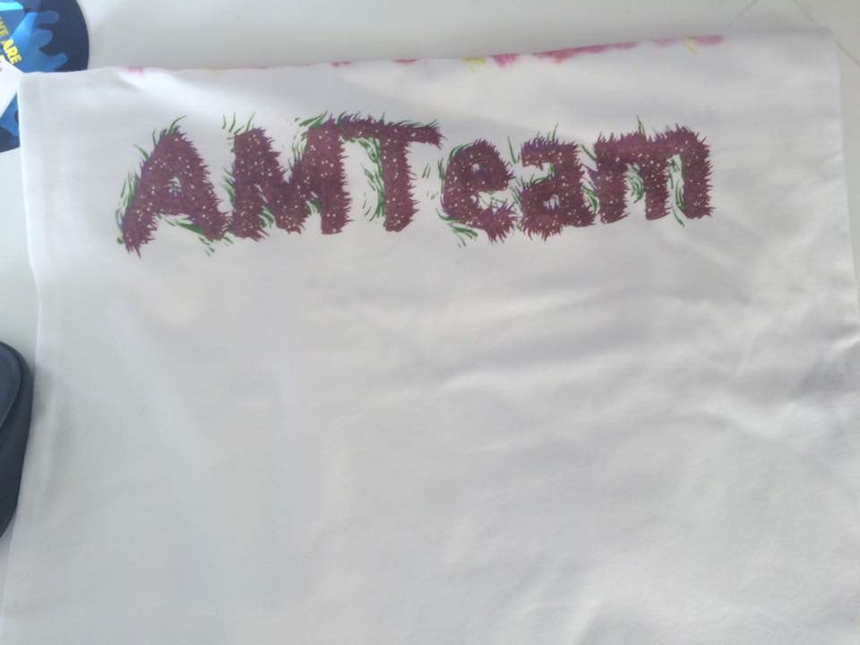
FullSizeRender IMG_6896


Code:

import processing.pdf.*;

import processing.serial.*;
import cc.arduino.*;
Arduino arduino;
int lightReading=0;
int lightReading2=0;

int maxParticles = 1000; // the maximum number of active particles
ArrayList <Particle> particles = new ArrayList <Particle> (); // the list of particles
int drawMode = 0; // cycle through the drawing modes by clicking the mouse
int colorMode = 0;
color BACKGROUND_COLOR = color(255);
color PGRAPHICS_COLOR = color(255);
float fc001;
PGraphics pg;

color c;
int number;
void setup() {
size(1400, 720, P2D);
smooth(16); // higher smooth setting = higher quality rendering
// create the offscreen PGraphics with the text
pg = createGraphics(width, height, JAVA2D);
pg.beginDraw();
pg.textSize(300);
pg.textAlign(CENTER, CENTER);
pg.fill(PGRAPHICS_COLOR);
pg.text(“AMTeam”, pg.width/2, pg.height/2);
pg.endDraw();
background(BACKGROUND_COLOR);
arduino = new Arduino(this, Arduino.list()[1], 57600);
arduino.pinMode(2, Arduino.INPUT);
arduino.pinMode(3, Arduino.INPUT);
}

void draw() {
lightReading=arduino.analogRead(3);
fc001 = frameCount * 0.01;
addRemoveParticles();
// update and display each particle in the list
for (Particle p : particles) {
p.update();
p.display();
}

if (lightReading <600) {
drawMode = ++drawMode%4; // cycle through 4 drawing modes (0, 1, 2, 3)
colorMode = ++colorMode%4;
//stroke(color(random(255), lightReading2/4, random(255), 125));
background(BACKGROUND_COLOR); // clear the screen

// Set color
//colorMode = (int) random(4);

if (drawMode == 2) image(pg, 0, 0); // draw text to the screen for drawMode 2
//particles.clear(); // remove all particles
delay(100);
}
println();

lightReading2=arduino.analogRead(2);
fc001 = frameCount * 0.01;

switch(colorMode) {
case 0:
c = color(lightReading2/4, 3, 16, 125);
break;
case 1:
c = color(155, lightReading2/4, 17, 125);
break;
case 2:
c = color(lightReading2/4, 87, lightReading2/4, 125);
break;
default :
c = color(183, 207, lightReading2/4, 125);
}

//colorChange();
// update and display each particle in the list
for (Particle p : particles) {
p.update();
p.display();
}
//if (lightReading <500){
//colorMode = ++colorMode%4; // cycle through 4 drawing modes (0, 1, 2, 3)
//background(BACKGROUND_COLOR); // clear the screen
////particles.clear(); // remove all particles
//delay(100);
//}
}

//void mousePressed() {

// drawMode = ++drawMode%4; // cycle through 4 drawing modes (0, 1, 2, 3)
// background(BACKGROUND_COLOR); // clear the screen
// if (drawMode == 2) image(pg, 0, 0); // draw text to the screen for drawMode 2
// //particles.clear(); // remove all particles
//}

void addRemoveParticles() {
//remove particles with no life left
for (int i=particles.size()-1; i>=0; i–) {
Particle p = particles.get(i);
if (p.life <= 0) {
particles.remove(i);
}
//for (int i=particles.size()-1; i>=0; i–) {
//Particle p = particles.get(i);
//if (lightReading <800) {
// particles.remove(i);
//}
}
// add particles until the maximum
while (particles.size () < maxParticles) {
particles.add(new Particle(c));
}
}

void keyPressed(){
if(key == ‘s’){
println(“Saving…”);
String s = “screen” + nf(number,4) +”.jpg”;
save(s);
number++;
println(“Done saving.”);
}
}


///////////class – Particle
class Particle {
PVector loc;
float maxLife, life, lifeRate;

color c;

Particle(int c) {
getPosition();
// set the maximum life of the Particles depending on the drawMode
switch(drawMode) {
case 0: maxLife = 1.25; break;
case 1: maxLife = 1.0; break;
case 2: maxLife = 0.75; break;
case 3: maxLife = 0.5; break;
}
// randomly set a life and lifeRate for each Particle
updateColor(c);
life = random(0.5 * maxLife, maxLife);
lifeRate = random(0.01, 0.02);

}

void updateColor(color col) {
c = col;
}

//void updateColor(int colorMode) {
//
//}

void update() {
// the velocity/direction of each Particle is based on a flowfield using Processing’s noise() method
// drawMode 0: no extras (an xy-position will always return the same angle)
// drawMode 1: dynamic noise (an xy-position will return a slightly different angle on every frame)
// drawMode 2: rotation (the angle of each xy-position is globally rotated)
// drawMode 3: dynamic noise + rotation (combines drawModes 1 & 2)
float angle = noise(loc.x * 0.01, loc.y * 0.01, drawMode==1 || drawMode==3 ? fc001 : 0) * TWO_PI;
PVector vel = PVector.fromAngle(angle + (drawMode==2 || drawMode==3 ? fc001 : 0));
loc.add(vel);
life -= lifeRate; // decrease life by the lifeRate (the particle is removed by the addRemoveParticles() method when no life is left)
}

void display() {
//fill(255); // white fill
//stroke(lightReading2/4, 70, 120, 125);
stroke(c);
float r = 8 * life/maxLife; // radius of the ellipse
ellipse(loc.x, loc.y, r, r); // draw ellipse
}

// get a random position inside the text
void getPosition() {
while (loc == null || !isInText (loc)) loc = new PVector(random(width), random(height));
}

// return if point is inside the text
boolean isInText(PVector v) {
return pg.get(int(v.x), int(v.y)) == PGRAPHICS_COLOR;
}
}


SICK BEATZ//MAD STEPZ (final project by Dasha and Sanie)

Link to the Instructables tutorial, for a more thorough description on how to make this happen.

Here is a tutorial on how to make a staircase musical instrument that makes sick beatz and produces generative art.

First, we had to make pressure sensors that would serve as the buttons of our musical instrument. We decided to make 4. For each sensor, we started with 2 pieces of neoprene and a piece of resistive fabric (25cm x 25cm each).

IMG_6903

You will also need two small pieces of conductive fabric to connect snap buttons and wires to.

IMG_6906

The first step after preparing the materials is sewing with conductive thread. We made parallel lines throughout both pieces of neoprene fabric.

IMG_6907

IMG_7168

Next step is to place the resistive fabric in between the two layers of neoprene with conductive thread, so that the parallel lines are going in different directions.

IMG_6942 IMG_6938IMG_6940

Then we attached to snap buttons to two corners (doesn’t matter which ones, as long as they’re not in the same corner) of the neoprene, that went through two small pieces of conductive fabric. The conductive fabric has to touch the conductive thread. We also connected wires to the snap buttons before the attachment that are then going to go to the lilypad.

IMG_6936 IMG_6937

IMG_7190

For more informations about how to connect the snap buttons, you can click here.

Once you’ve connected the wires you should test whether the sensor actually works. For that you first attach one of the wires to +, and another one to a 10K resistor and to -, and to an analog pin (A). You can see how it’s don in the scheme below:

scheme

To check that it works you can use the code seen in the photo below (if it works the values on the bottom of the screen in the console will change when you press the pressure sensor). You can copy it from this window or find it in processing examples called “arduino input sensor change”:

Screen Shot 2015-12-07 at 16.00.46 Screen Shot 2015-12-07 at 16.00.33

Here come the last steps: add foam on top of the sensor, once you’re sure that it works, and cardboard or thin wood on the bottom just to make it sturdy on the bottom.

IMG_7172

Lastly, find any fabric you like and cut out two 30x30cm squares to cover the foam, wood and pressure sensor. Make a whole in the fabric that the wires would go through and sew it all together!

IMG_7176 IMG_7179 IMG_7187

IMG_2343

IMG_2363

IMG_2367

IMG_2366

The finished result will look something like this:

IMG_2371

Then repeat all of the steps 3 more times to create 4 identical pressure sensors.

The code for Processing can be found on GITHUB. Add the data .wav files to the sketch, if you want to use our tracks. For Lilypad use All Inputs Firmata example code.