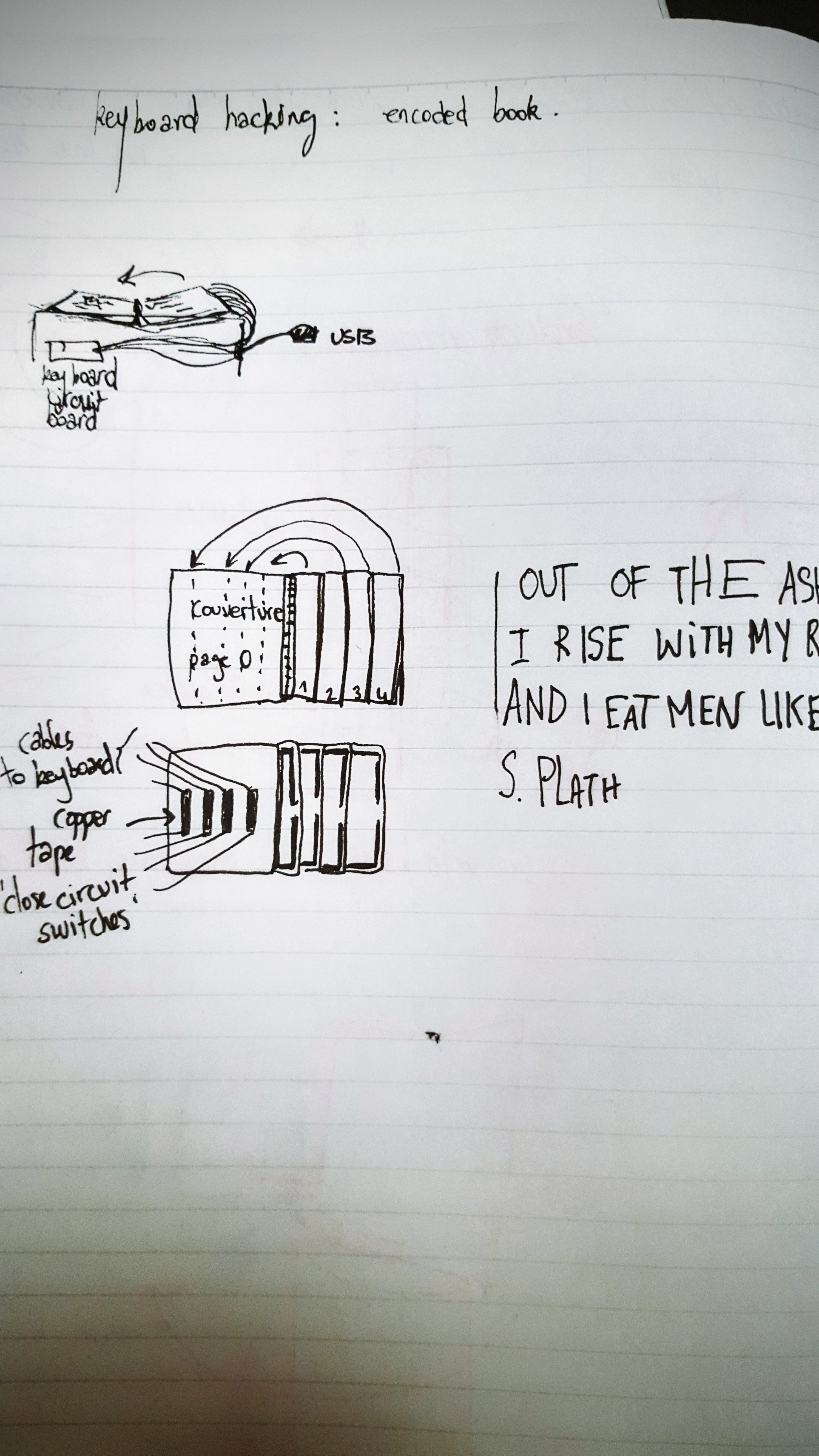
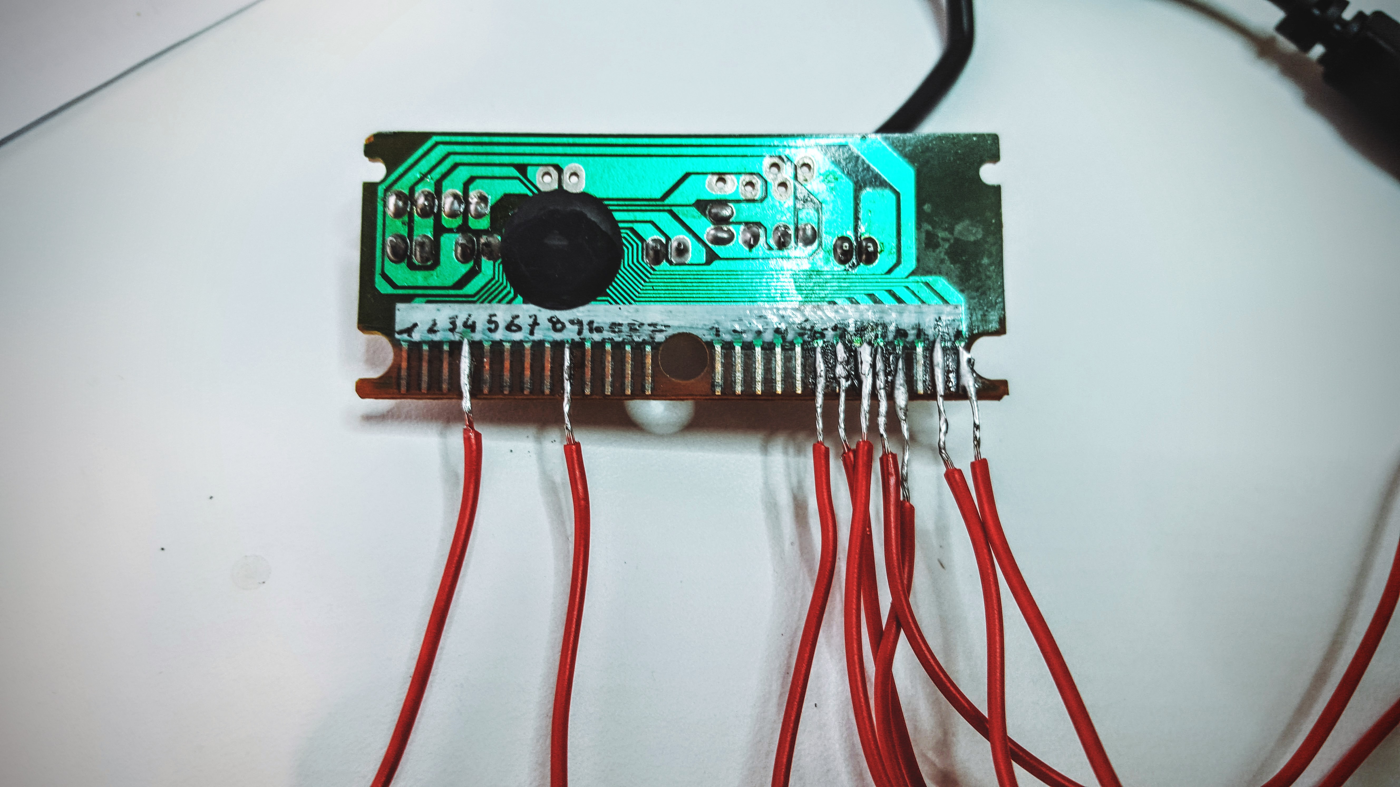
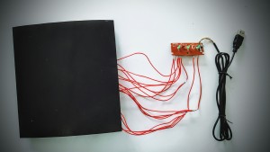
First step: Open the keyboard, take the circuit board out with the USB cable. Sand off delicately the black varnish on the straight lines at the bottom of the circuit board.
Second Step: Open a text edit page and test “line combinations” . One cable links one line from the left and one line from the right. Note down the combinations found.
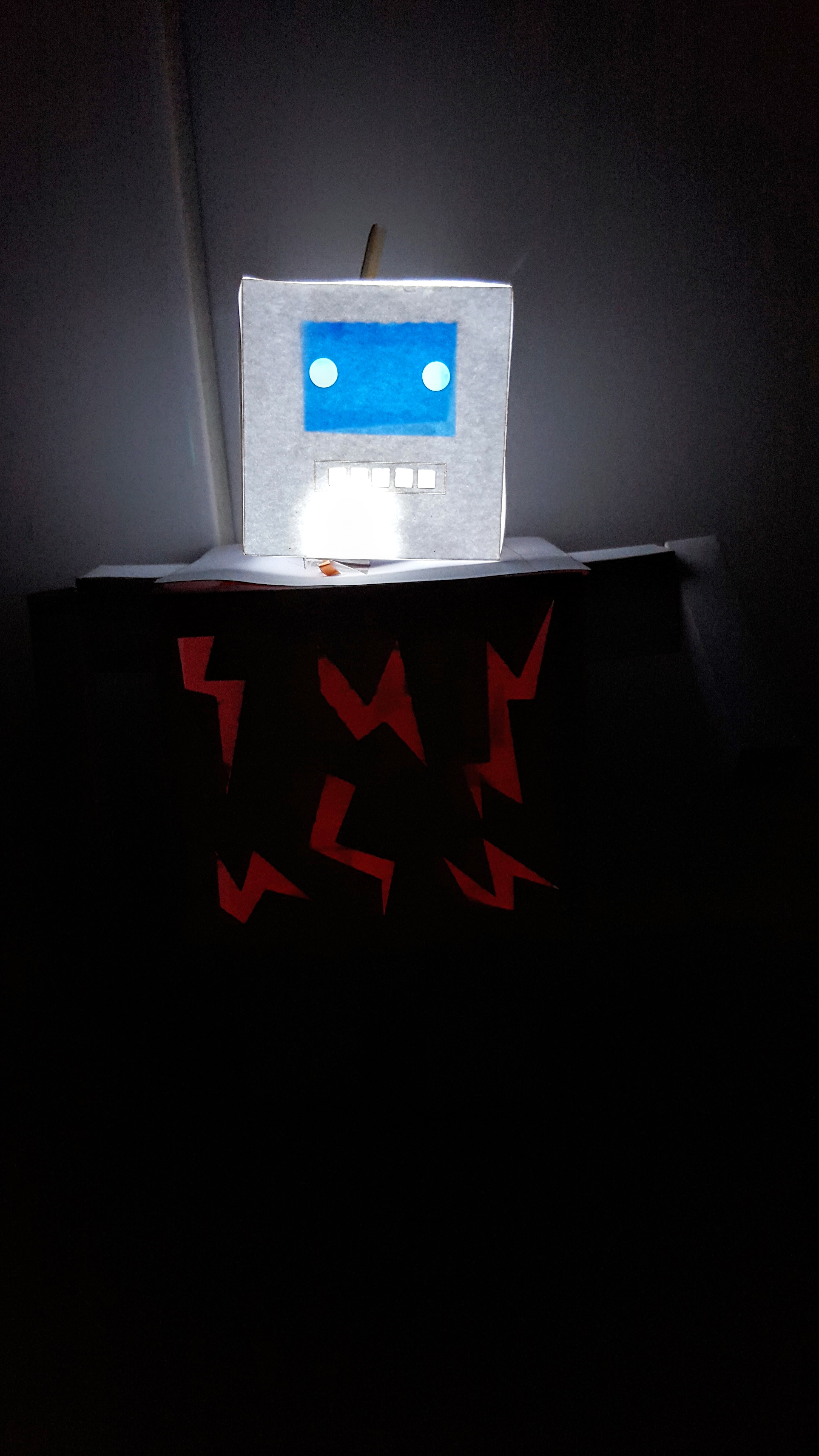
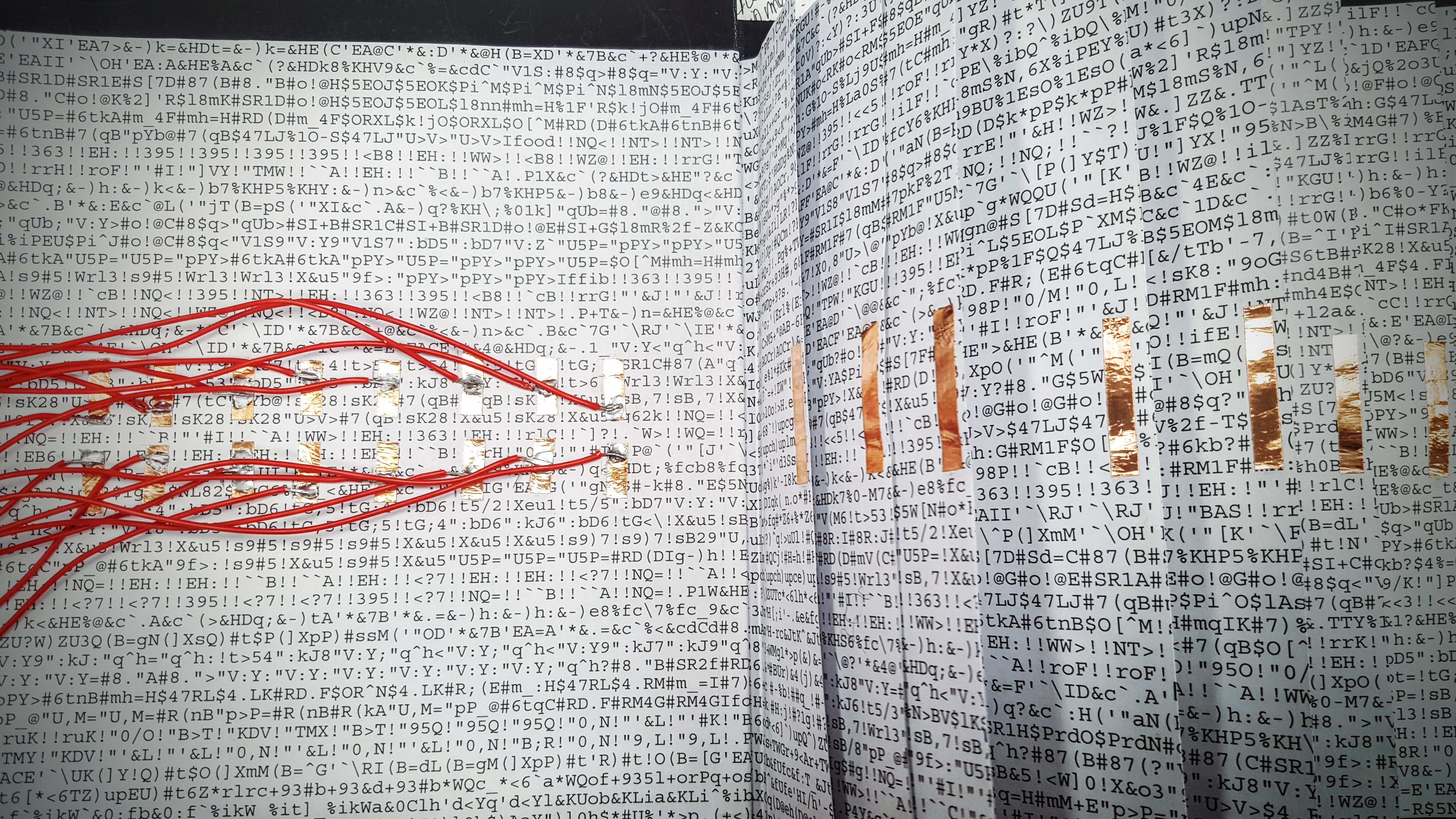
Step 3: Build the project. Encoded Book is a project that creates an electronic book. It is built out of pages with no meaning, a set of letters and signs that follow each other without any recognizable pattern.
As you turn the pages of the book, the contact is made with the keyboard, and a story appears on the screen.
I chose to display a tiny poem written by Sylvia Plath:
“Out of the ash I rise with my red hair And I eat men like air…”
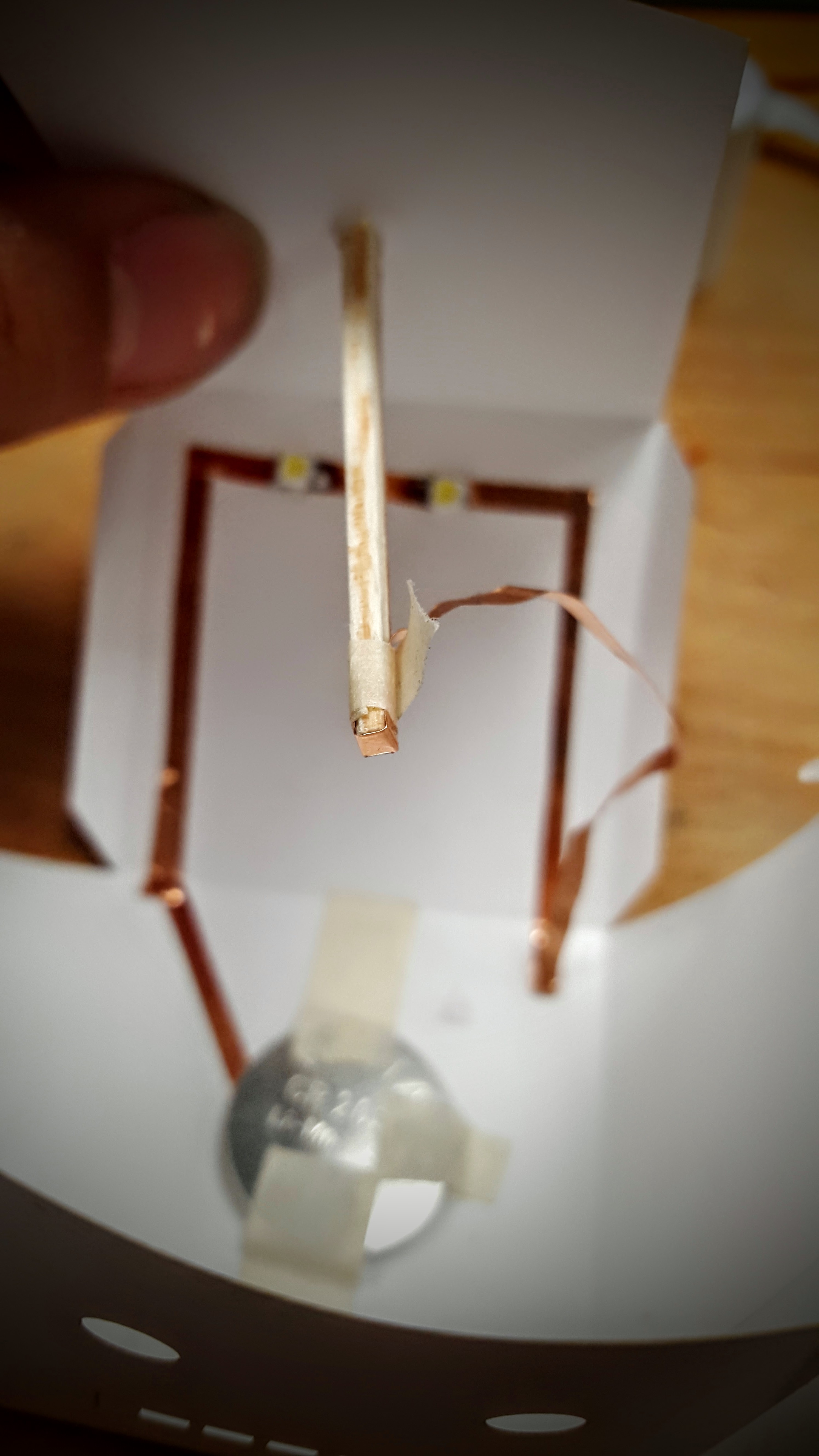
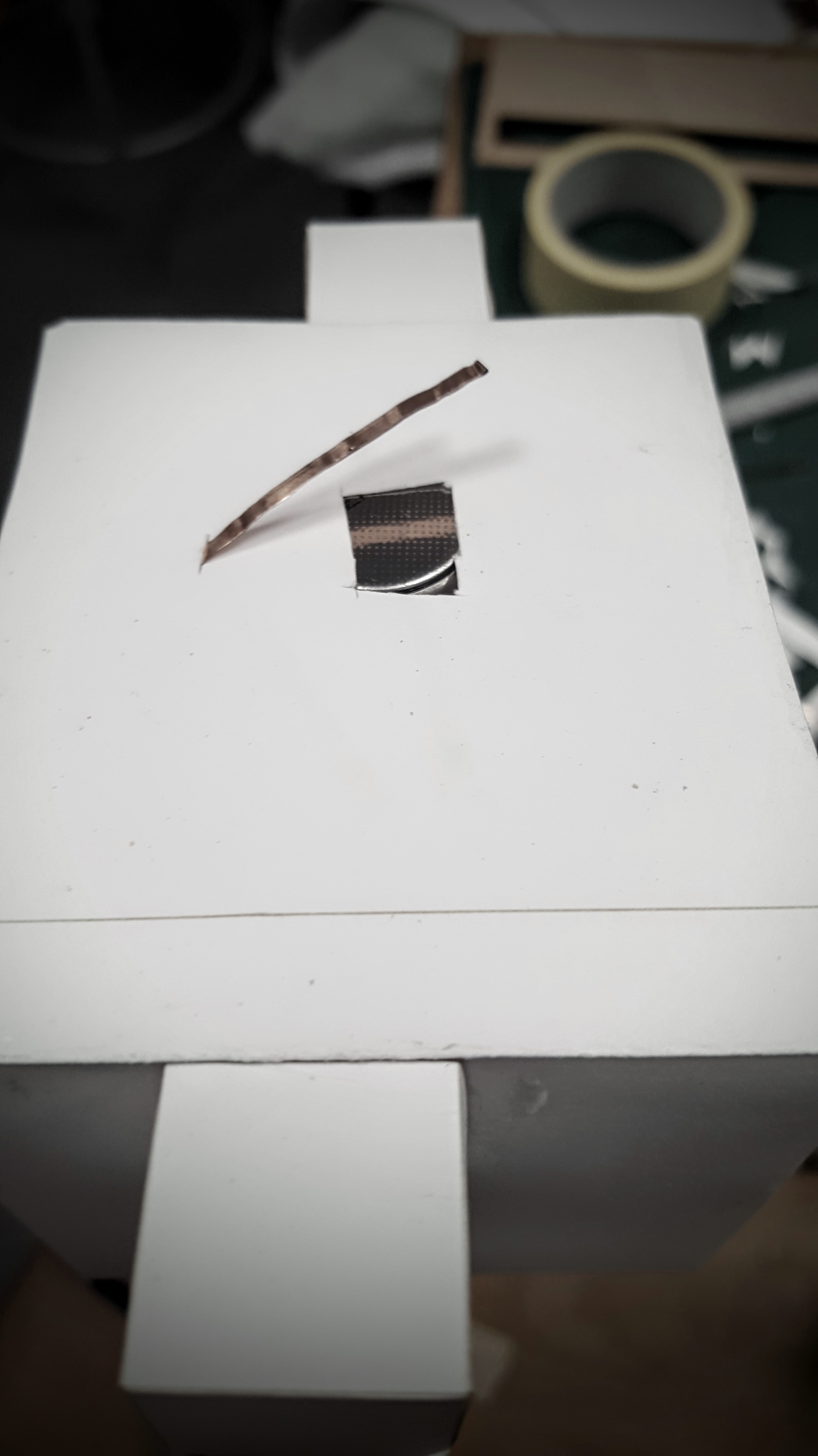
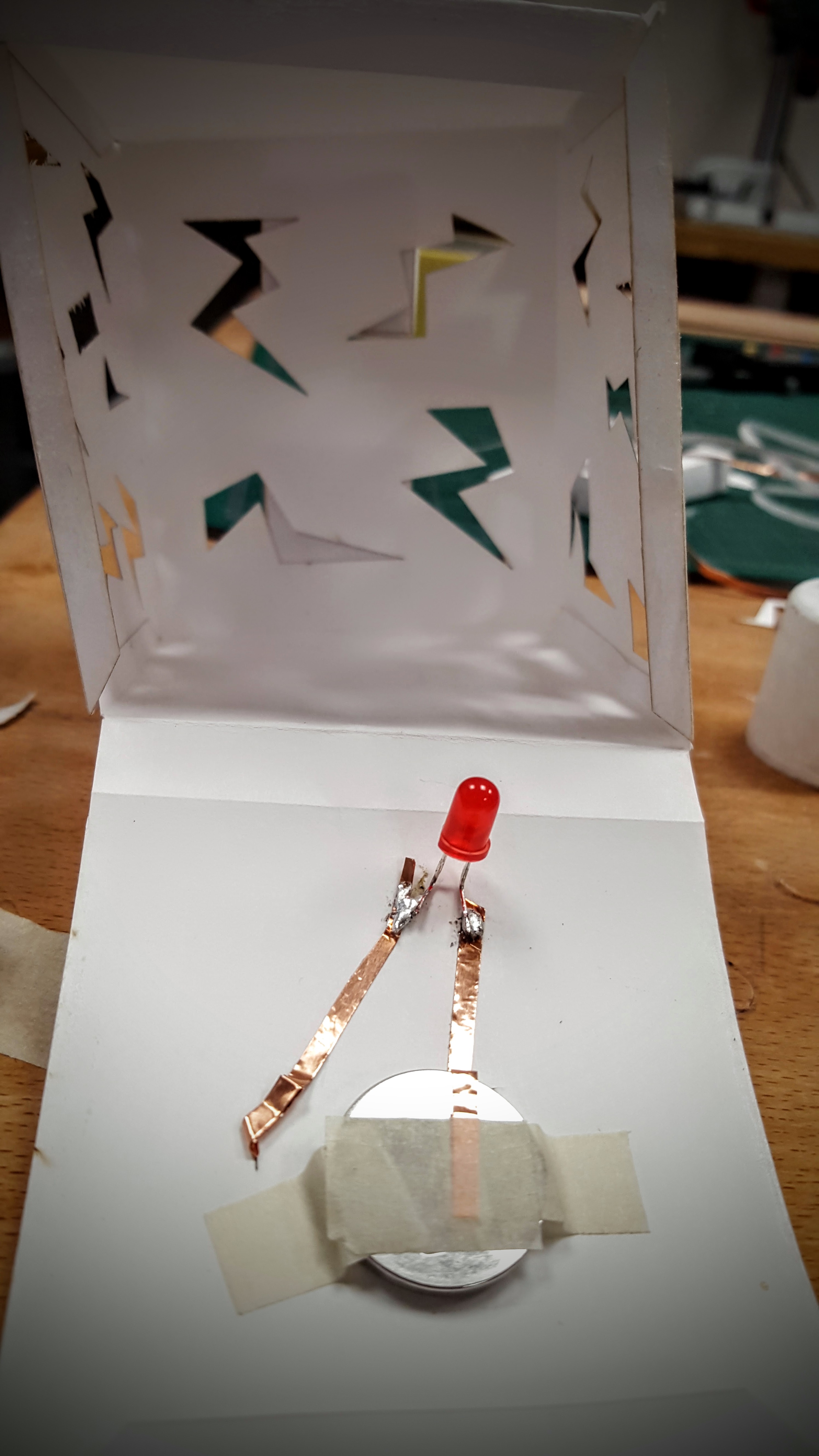
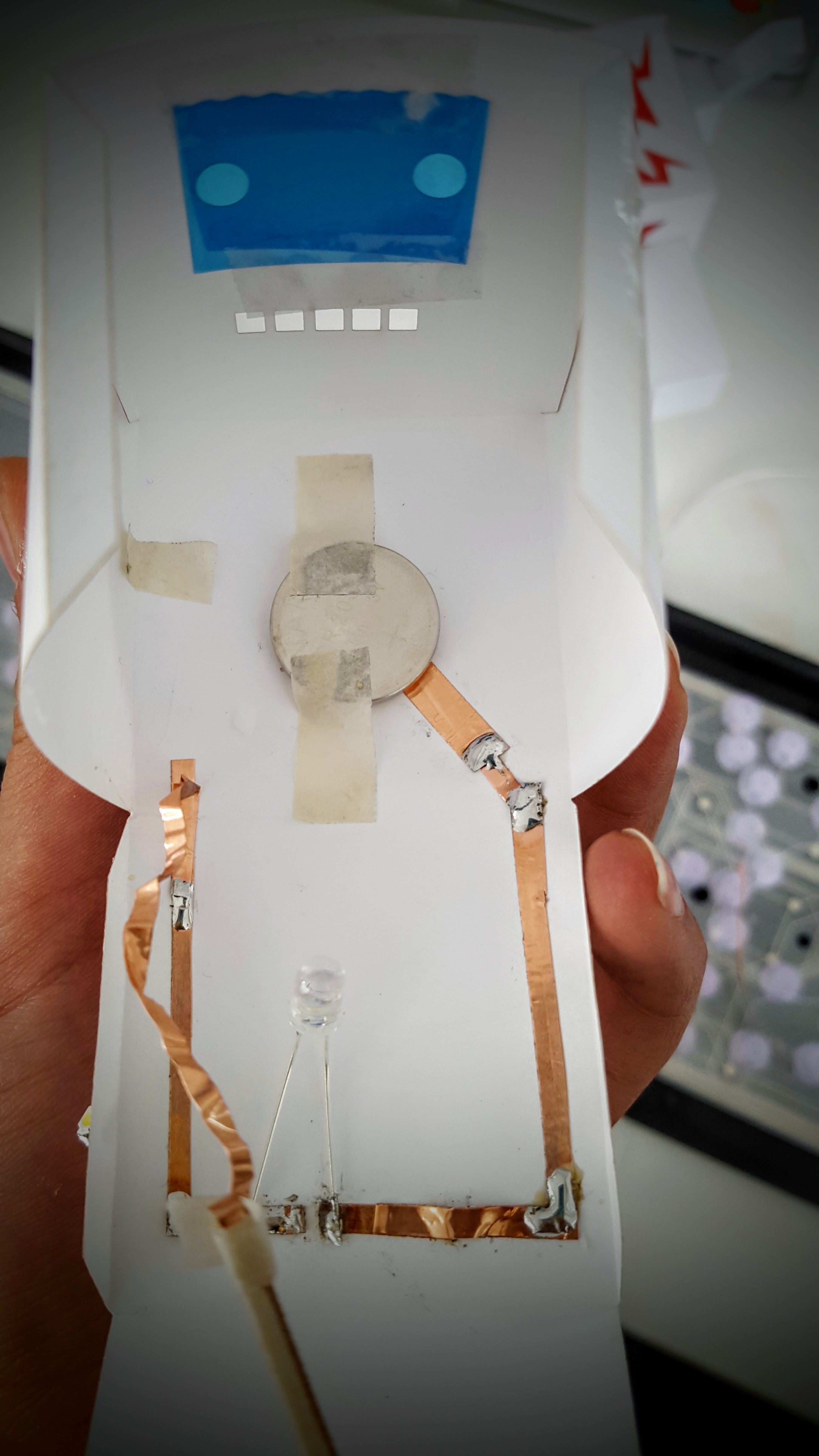
The book is binded, and between each page I built a circuit that is then glued down. The only thing shown is two parts of copper tape that will be used as a switch as the pages are turned.
This is the right way to put the copper tape, after realizing my circuit was still opened when turning the pages (duh):
Each page is attached to the correspondant combination of lines on the keyboard circuit board.
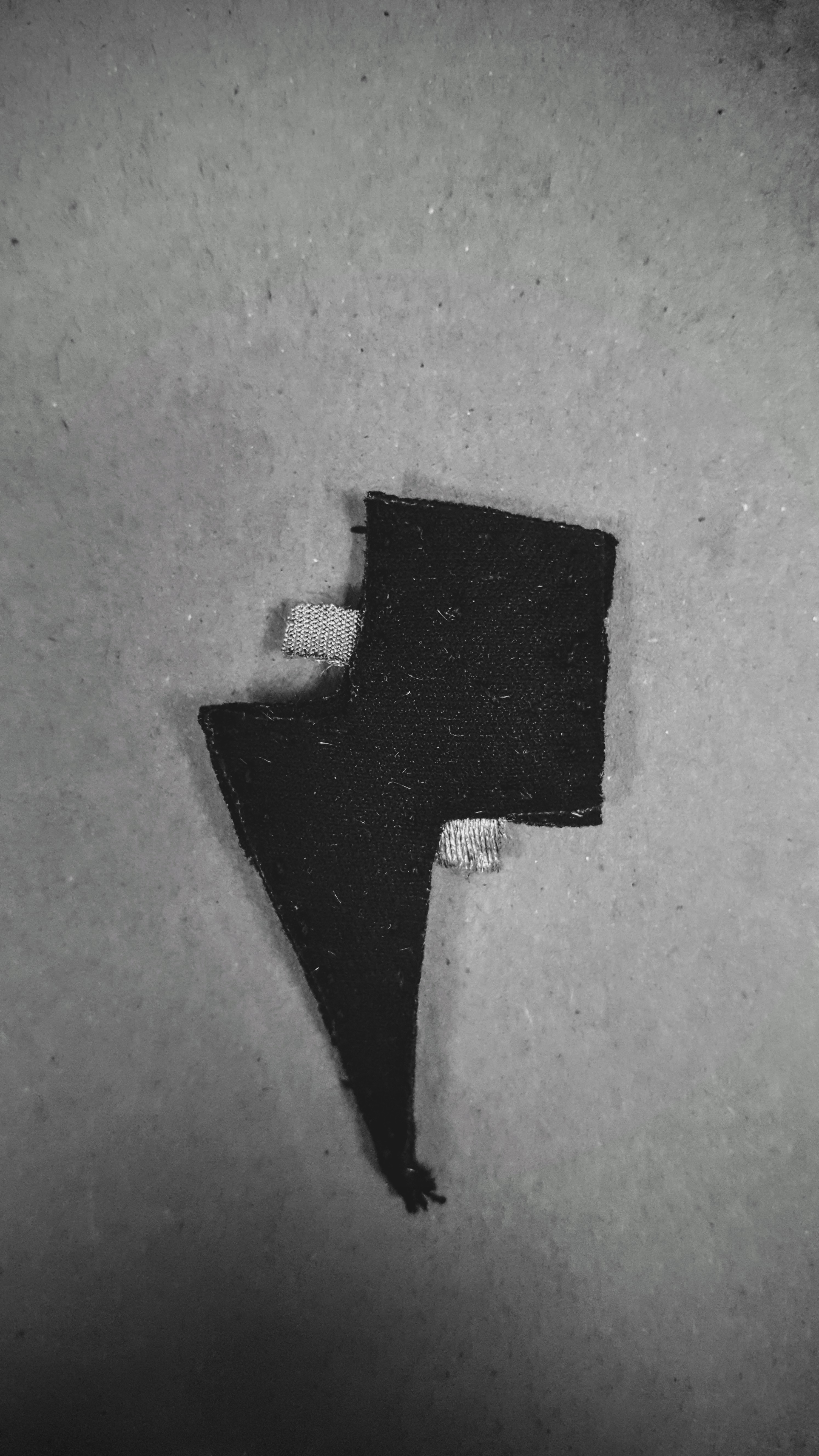
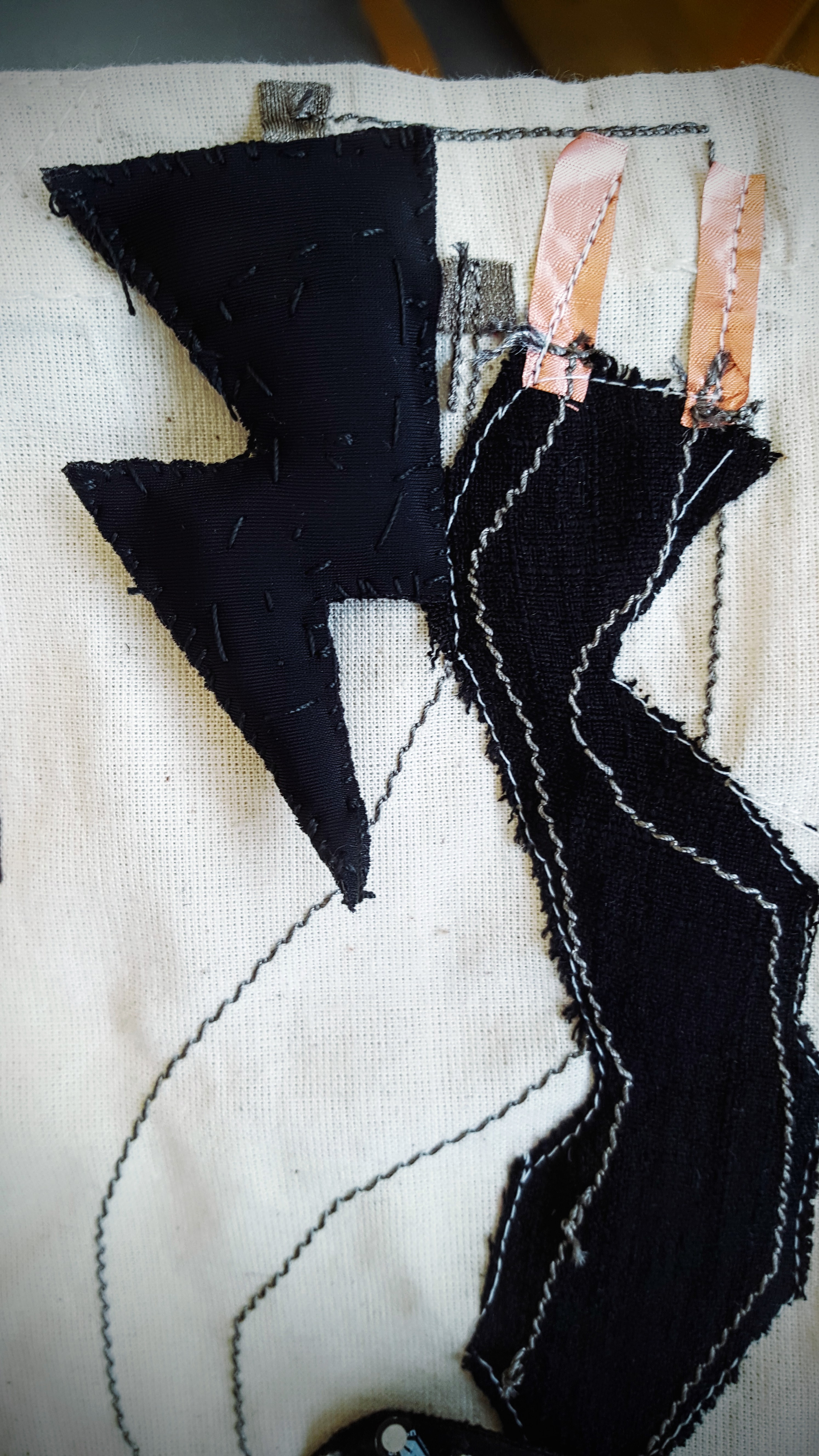
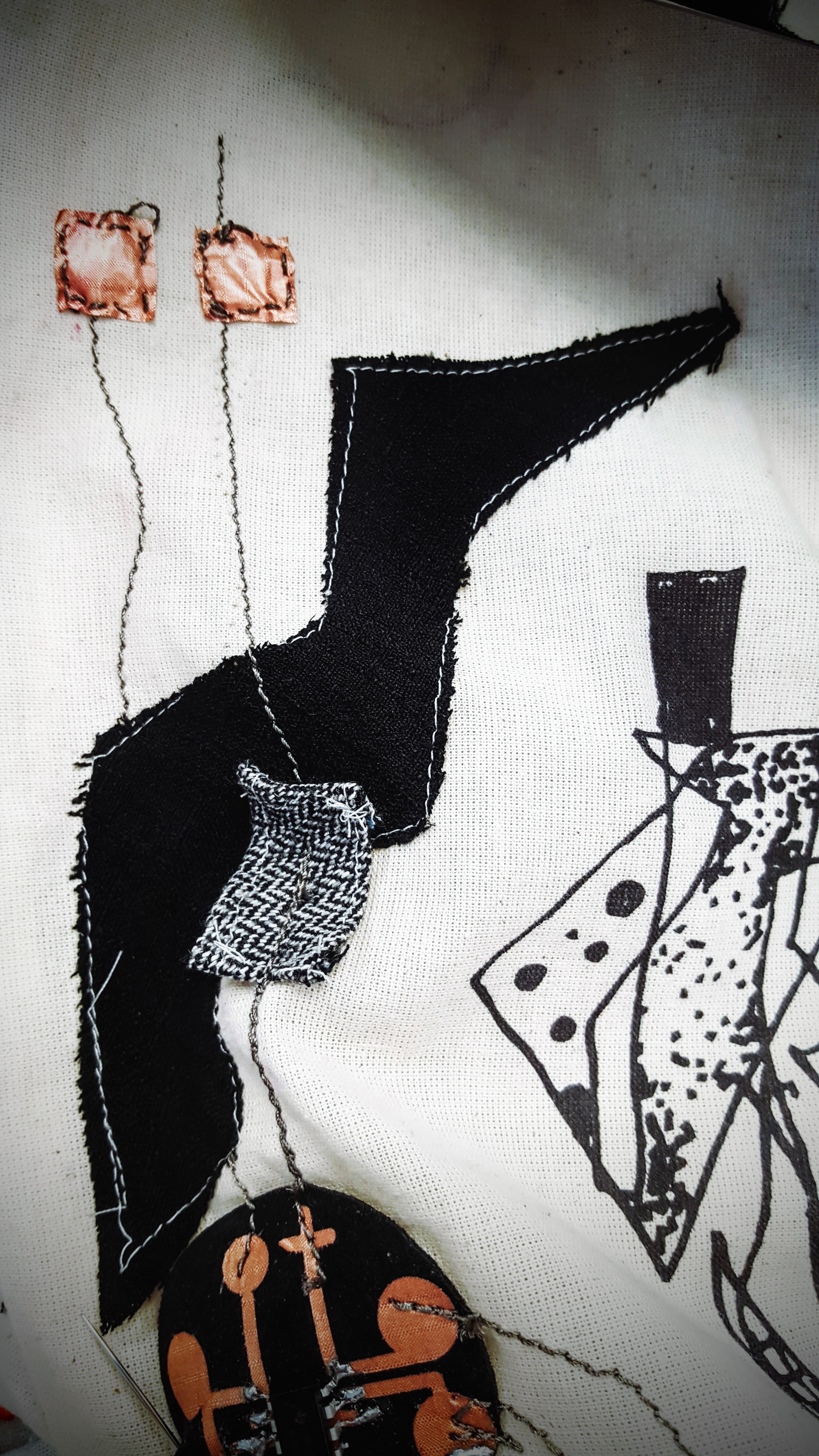
Pressure button made out of conductive fabric. First layer is normal fabric, like neoprene. The second one is a piece of conductive fabric (silver one) that is then covered by a resistive fabric made out of carbon. On the other half of the ray, another piece of conductive fabric is sew. Then the two sides are put together.
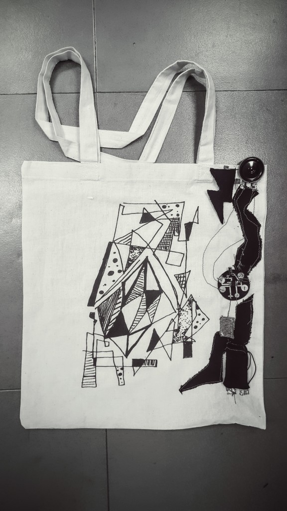
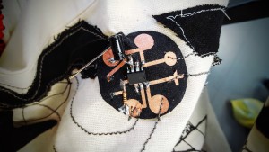
The ” I hate you – noisy totebag” is made with a Textilo: circuit fabric board ideal for sewing on garment.
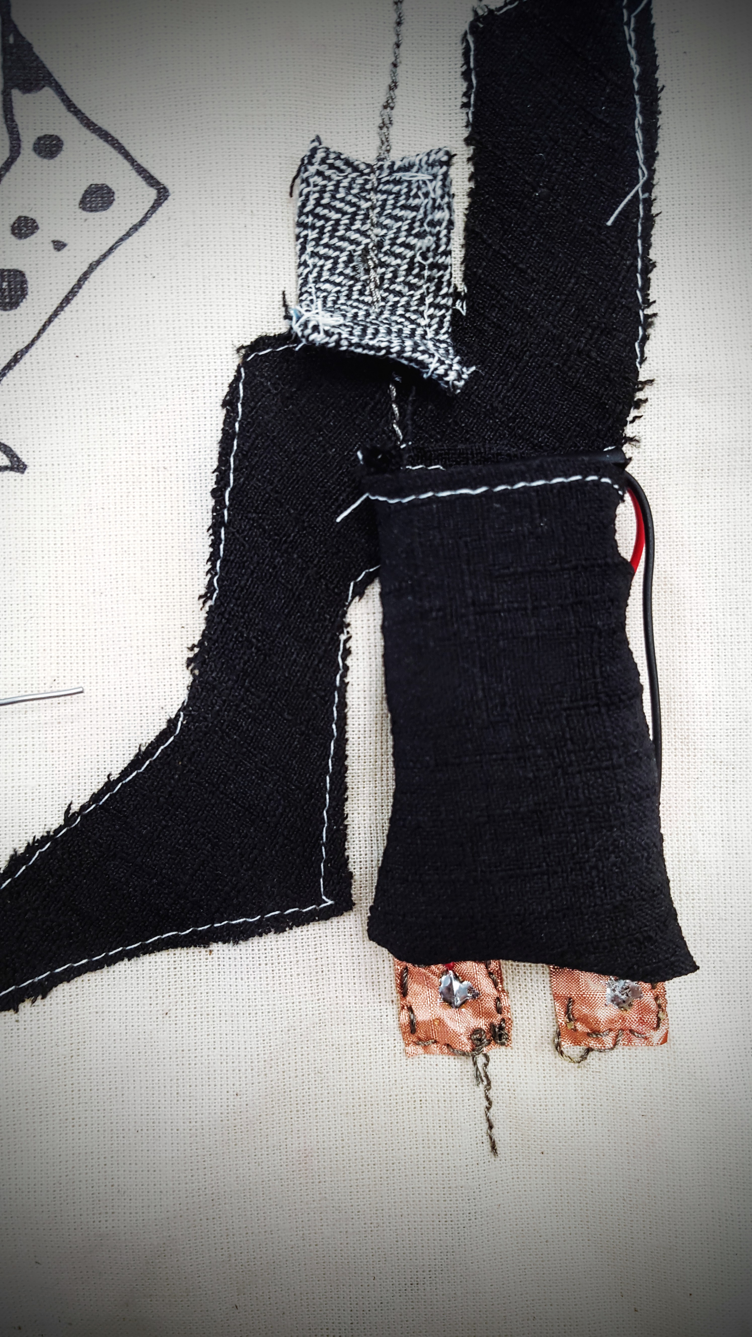
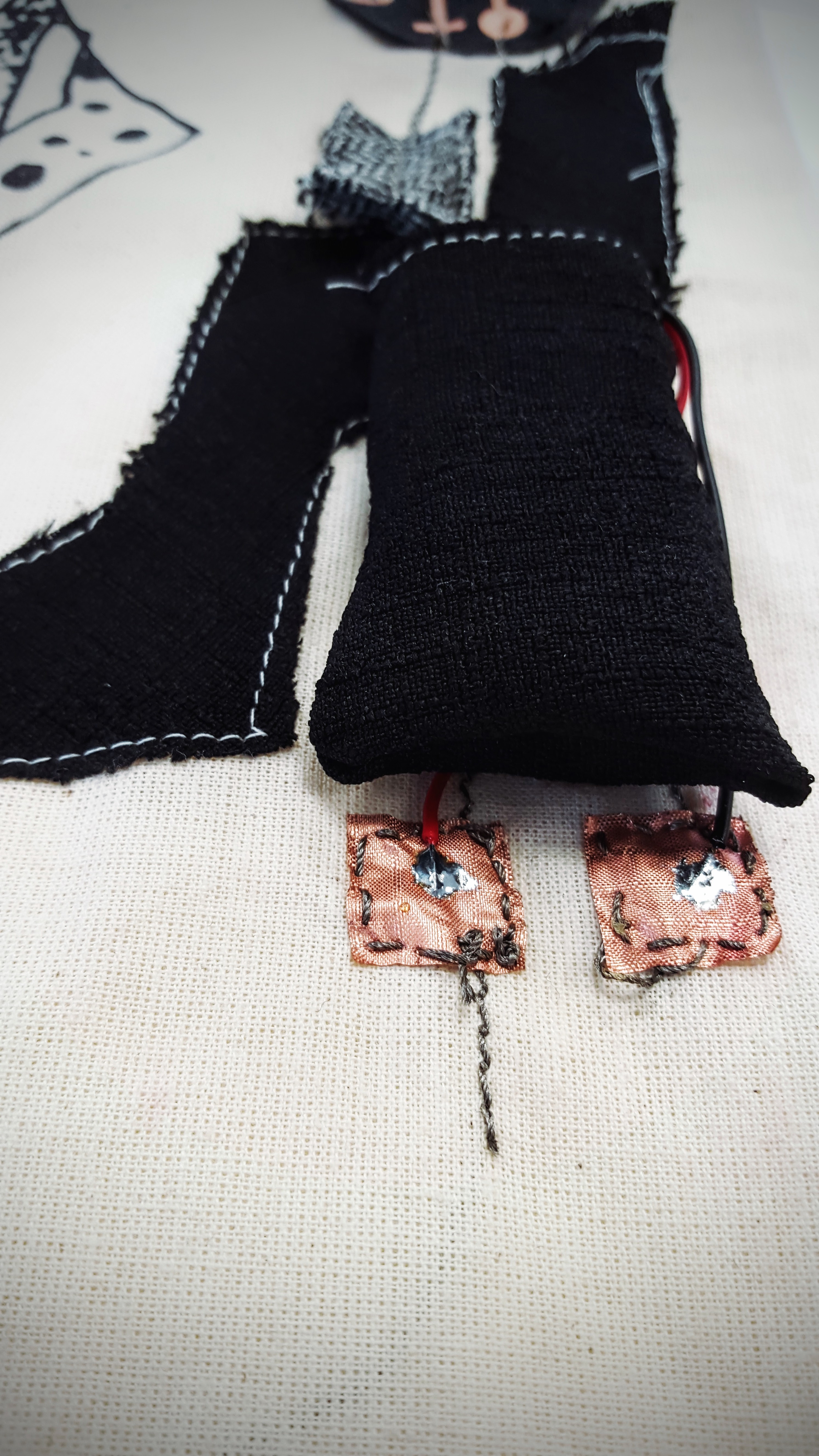
A pressure sensor is attached on the side with the resistance with conductive thread:
The side with the capacitors is connected to a little speaker with conductive thread. Adding extra bits of copper fabric allows to solder the speaker. To maintain it in place and avoid it from falling, I also added some velcro.
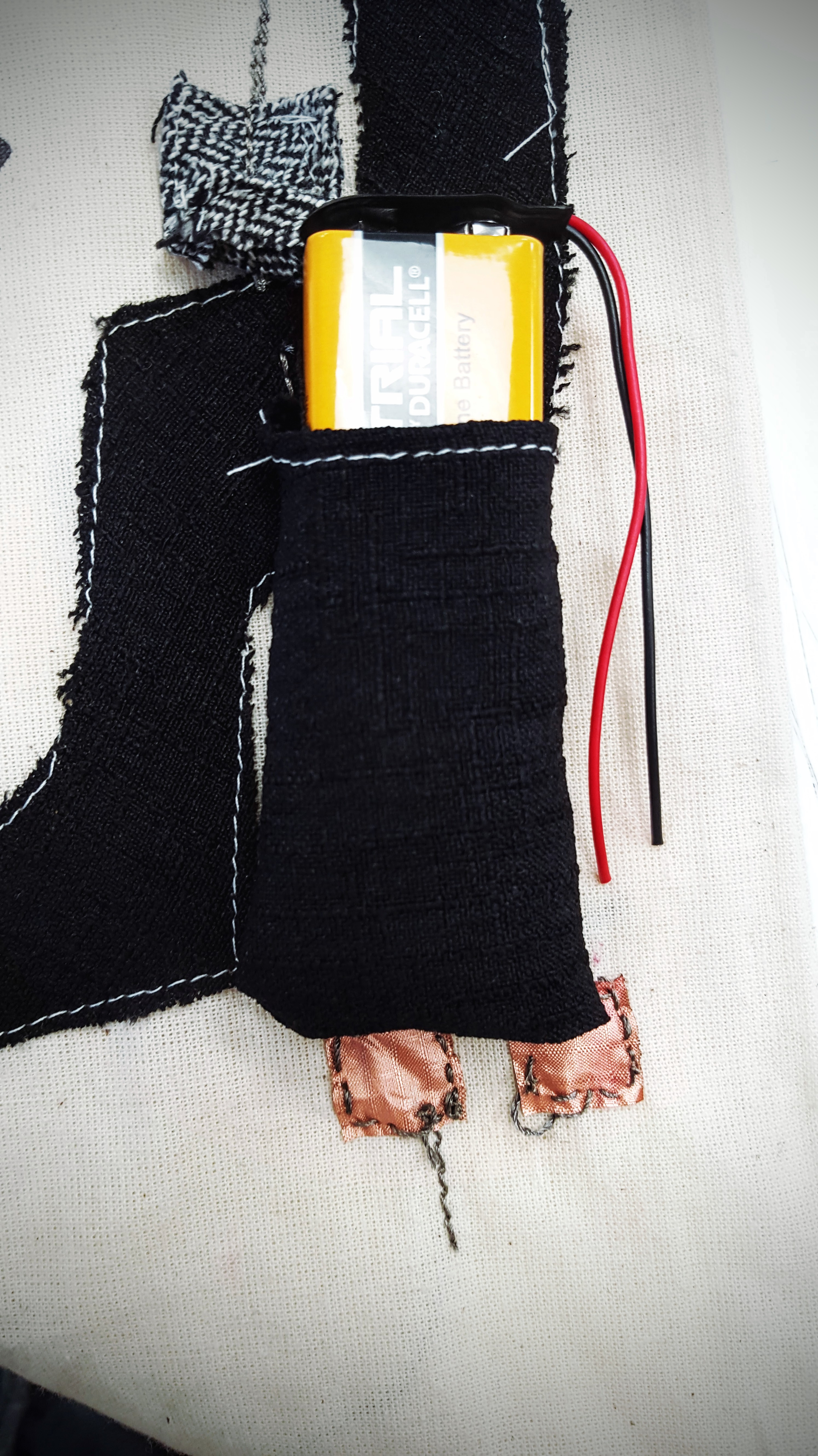
The battery is hidden in a little pocket. The wires are soldered to the extra copper fabric, connected with conductive thread to the + and – of the Textilo board.
The ” I hate you – Noisy Totebag” is activated with a button.
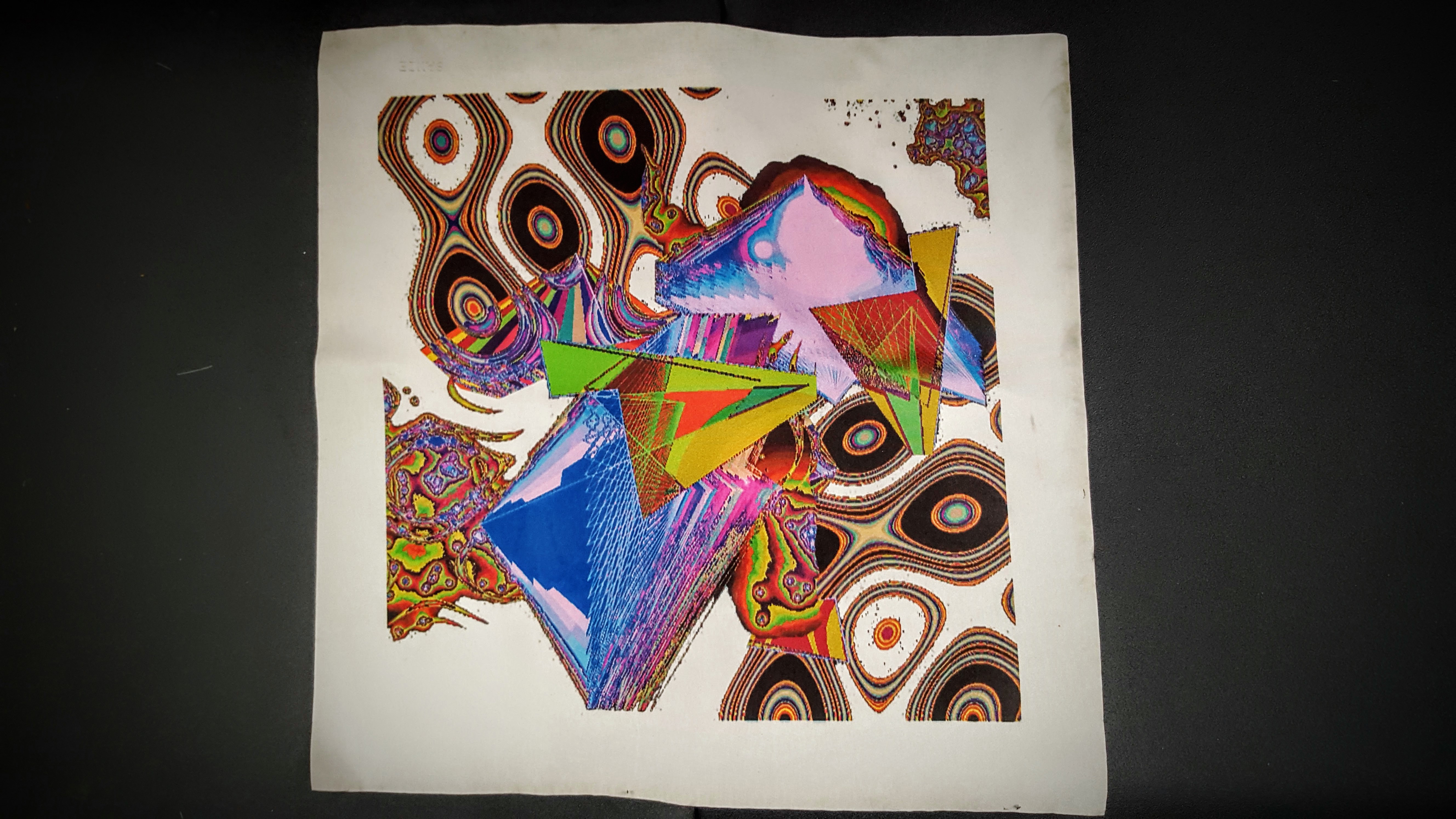
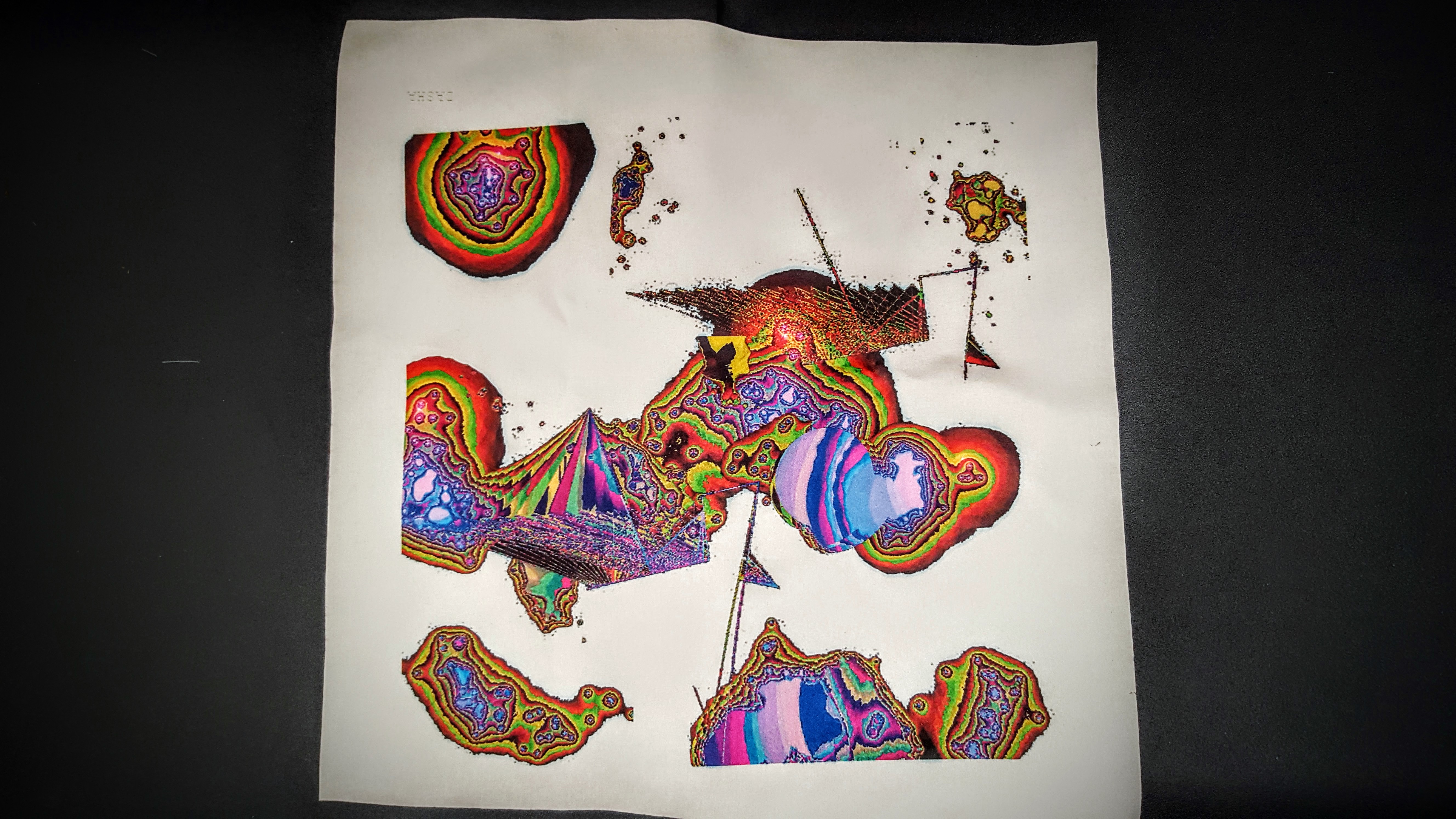
For this project, I created a Breathalyzer which draws colorful shapes as you exhale on it. The drawings vary depending on whether you had alcohol or smoked before.
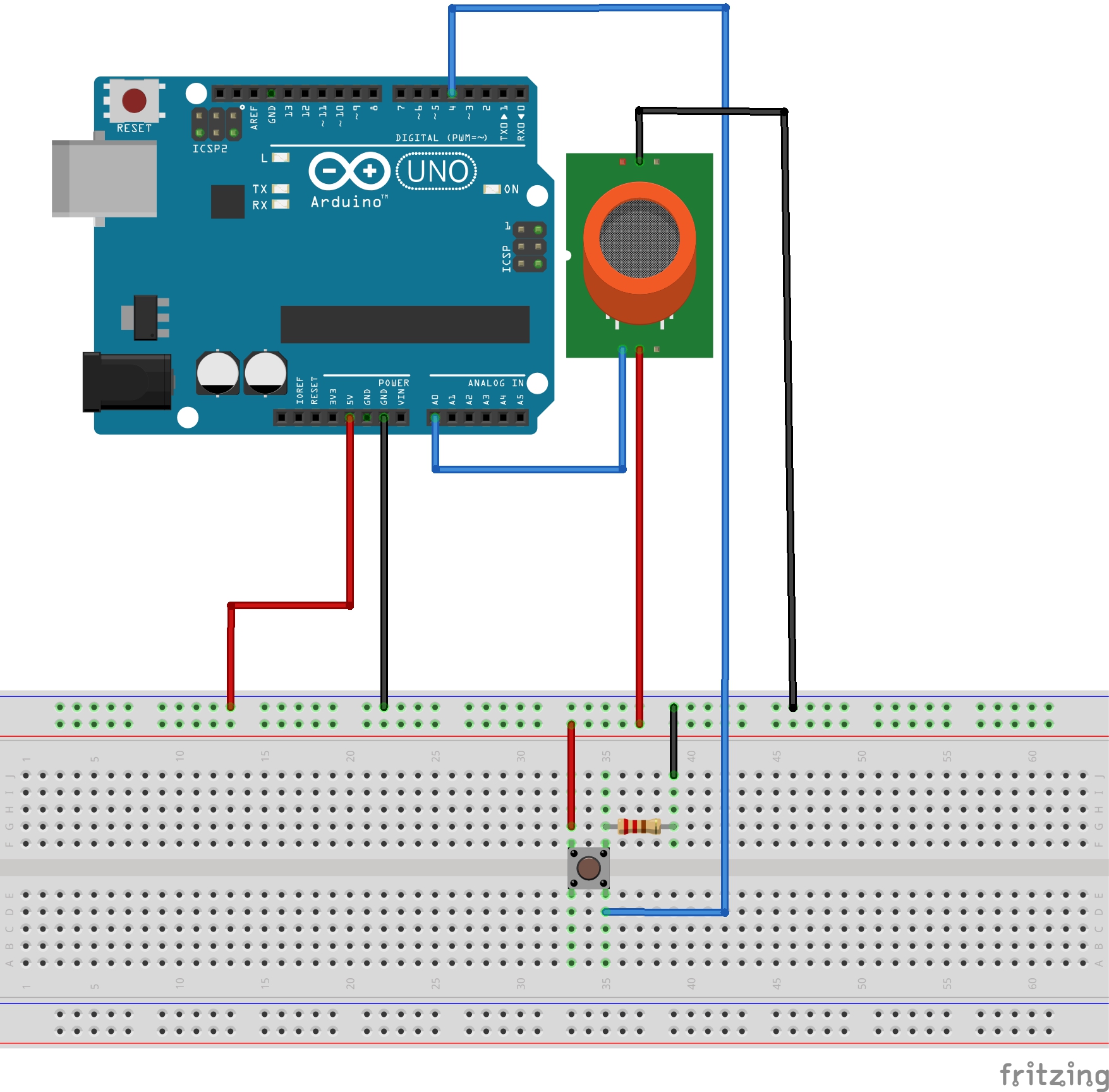
I used an MQ2 gaz sensor, a pushbutton, an arduino and processing.
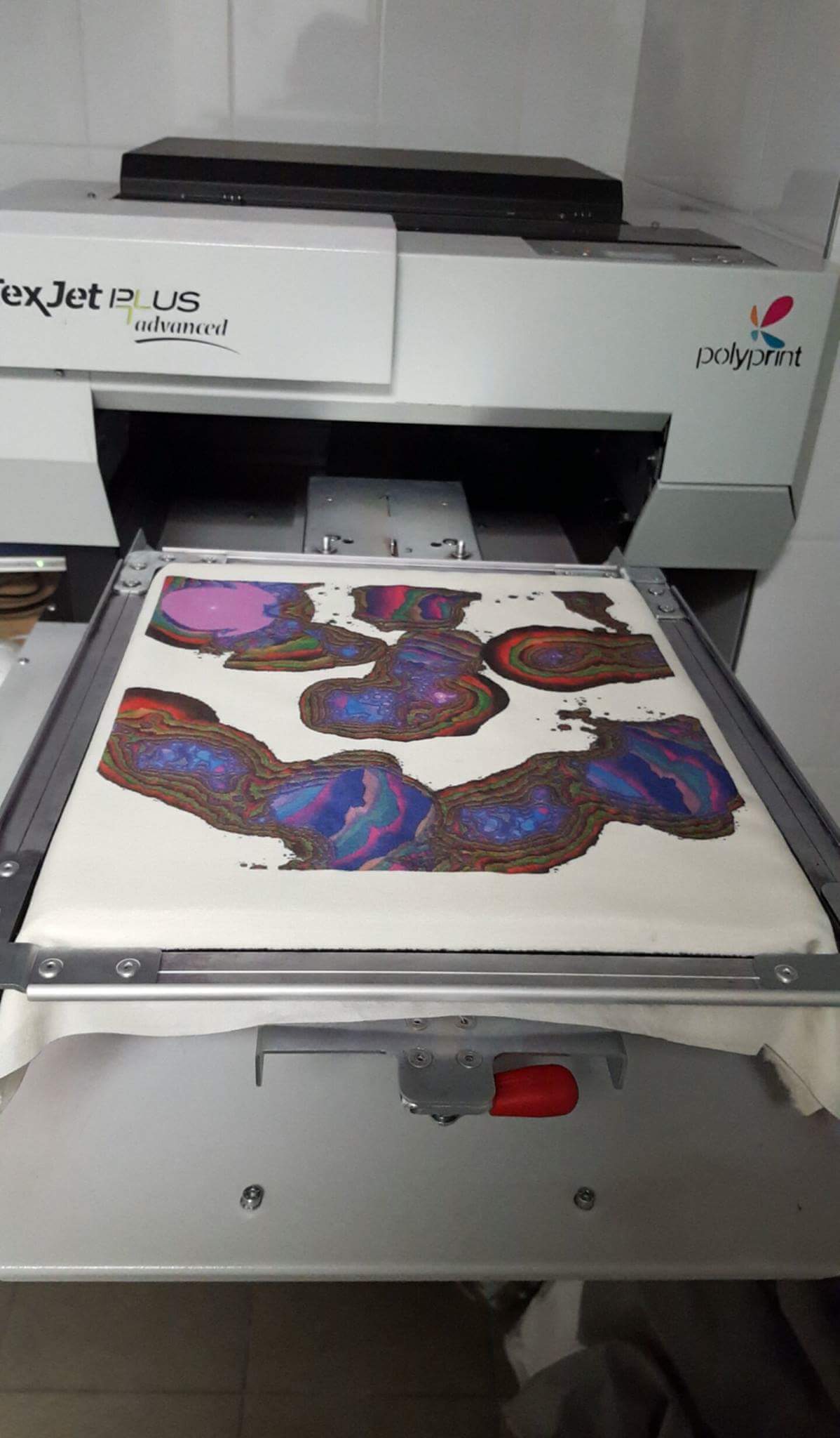
After saving a few of everyone’s breath drawings, I reassembled them in one file, which I printed on fabric to use as handkerchiefs.
Alcohol Value Reached
Decreasing Value From Alcohol to Normal
Smoke Value Reached
Breath Without Alcohol or Smoke.
I lasercut a box to put the sensor, adding a button that when pressed saves the screenshot.
Another hole on the side is used to pass the arduino serial cable.
The connexions to the MQ2 are as follow. My sensor had a four connexions: VCC (5V), GND, SIG (A0 pin) and NC. NC doesn’t need to be connected. The resistor used for the button is 10k Ohms.
After saving the images and recomposing them, the final result is printed on fabric (I used polyester).
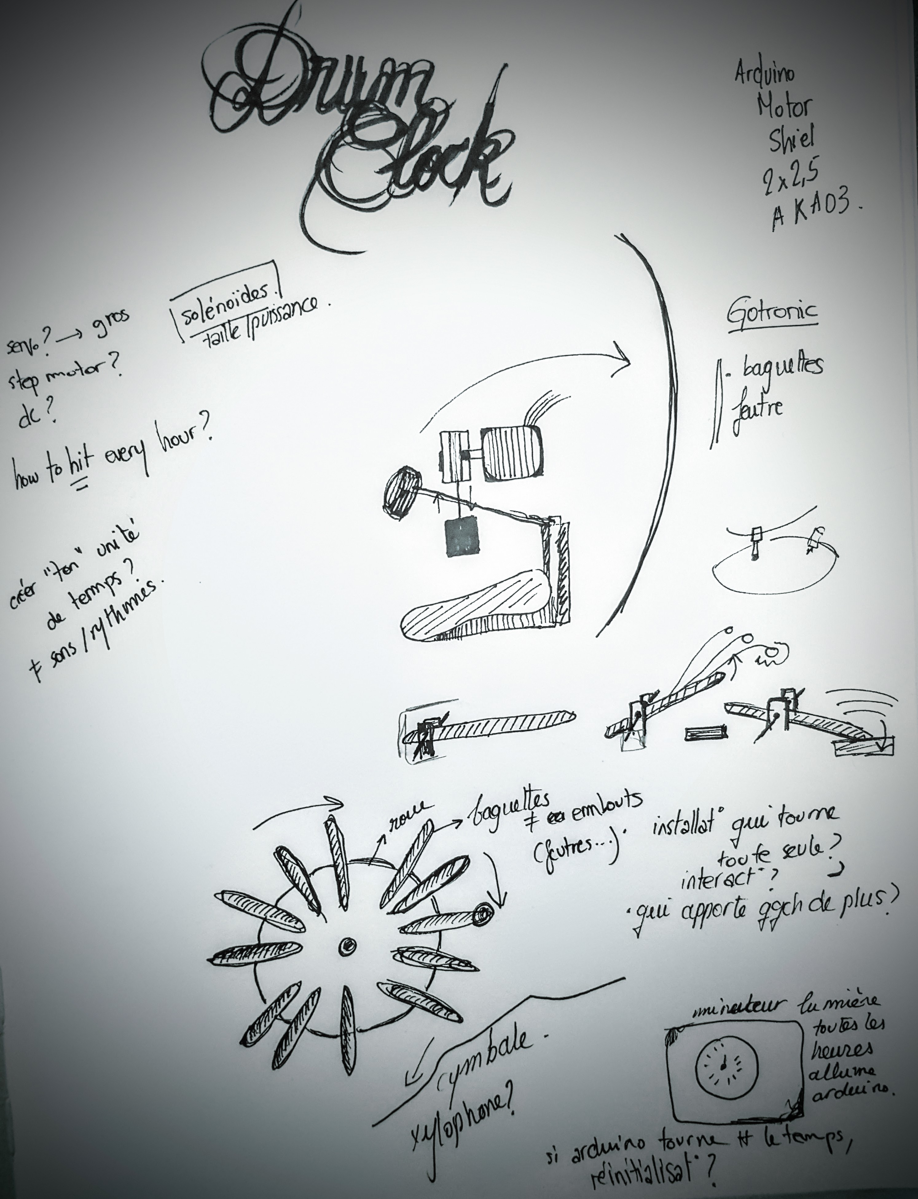
Music has always been of great inspiration to me, as well as the concept of time.
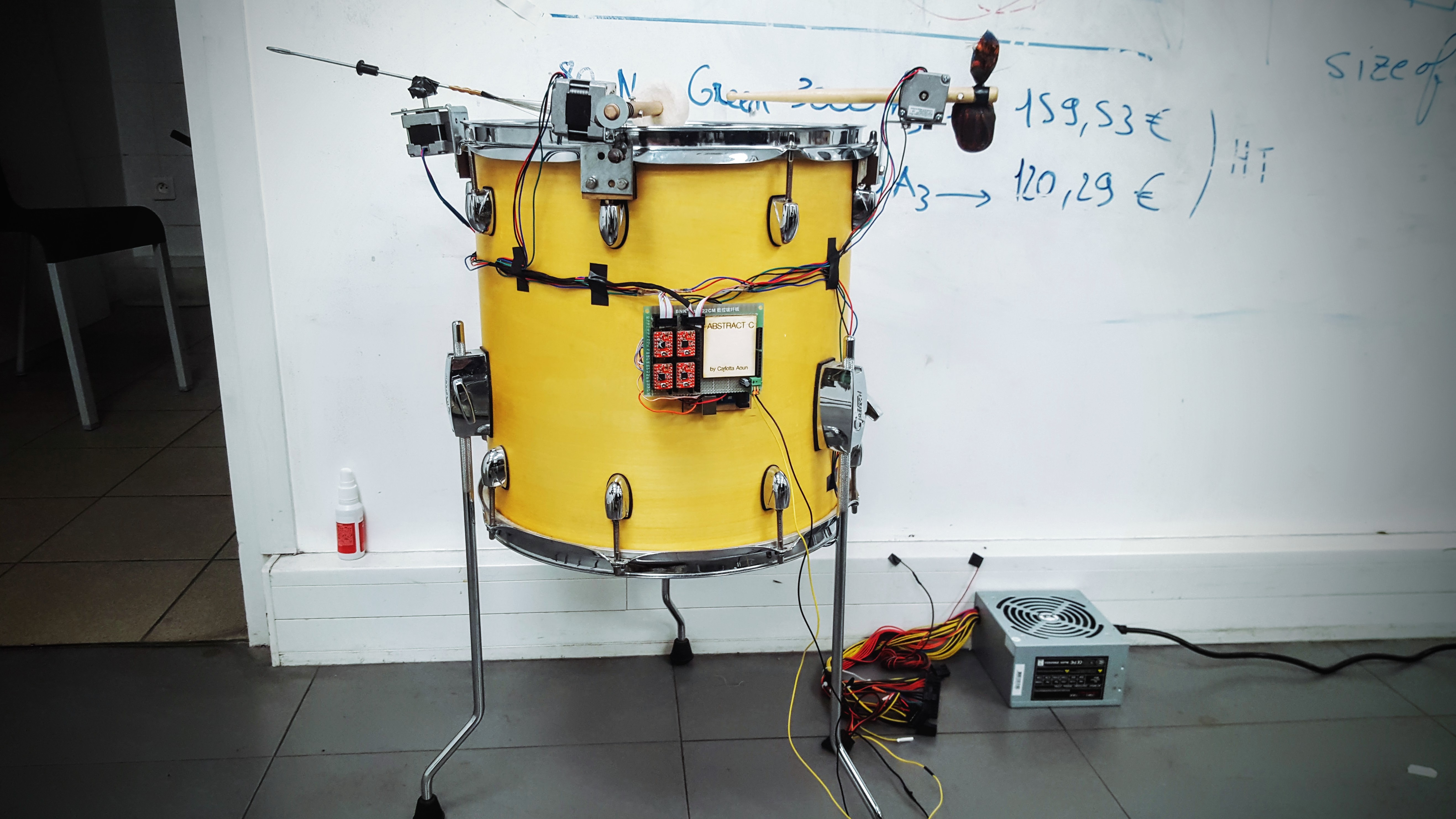
My project is about trying to make an abstract clock with a drum set. Abstract because it will play every hour, but you won’t actually know what hour it is.
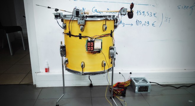
The idea is to have different elements (drum sticks, mallets, brushes, solenoids…) hitting the drums, driven by step motors and arduinos. The objects would start playing a random sample by hour. I plan to use a lamp timer to activate the arduino and launch the code every hour.
So far, I’ve been trying to get the motors to work, but they are not running on 12V, only 5V, which doesn’t give them enough force to hold the drumsticks.
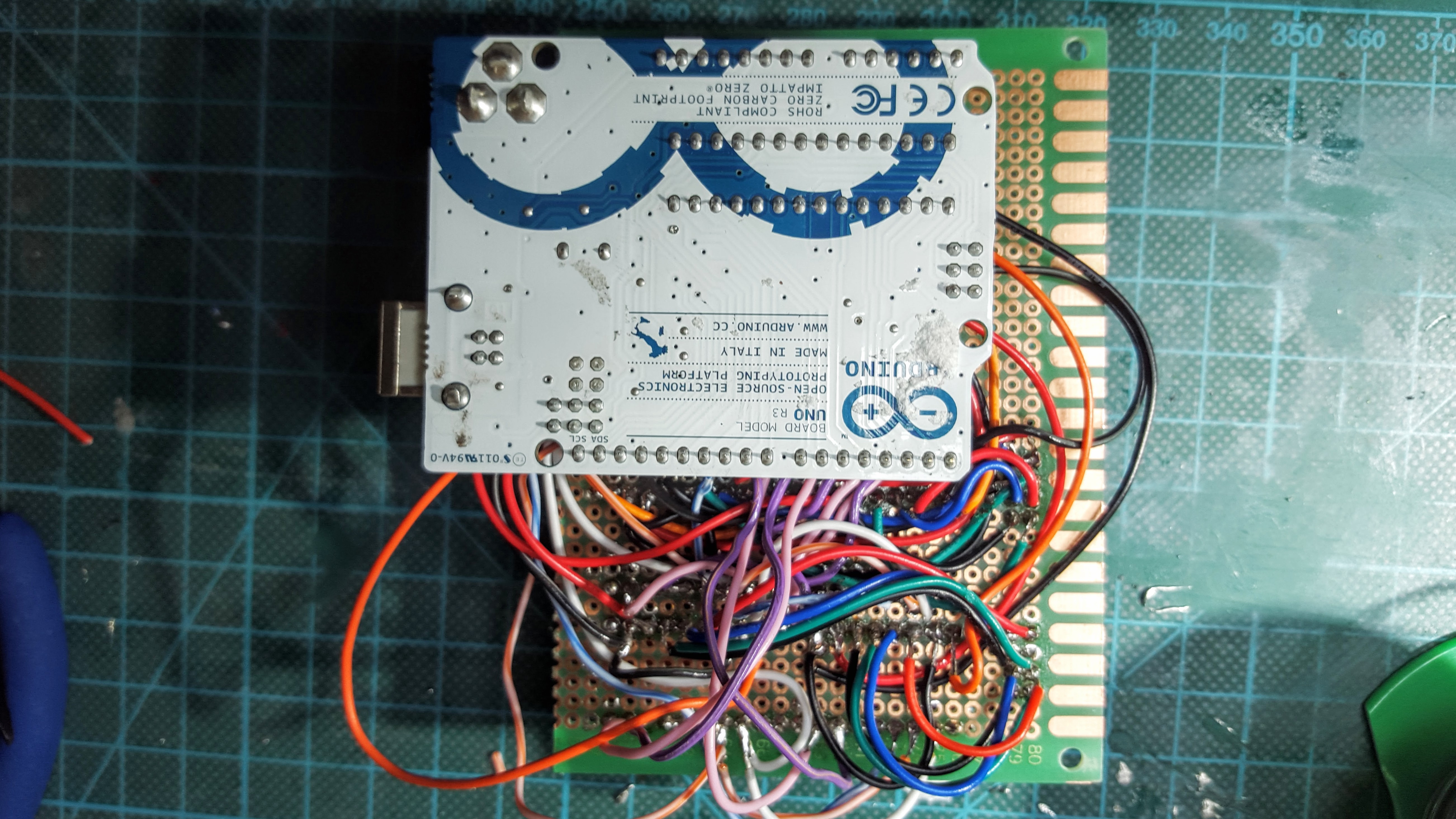
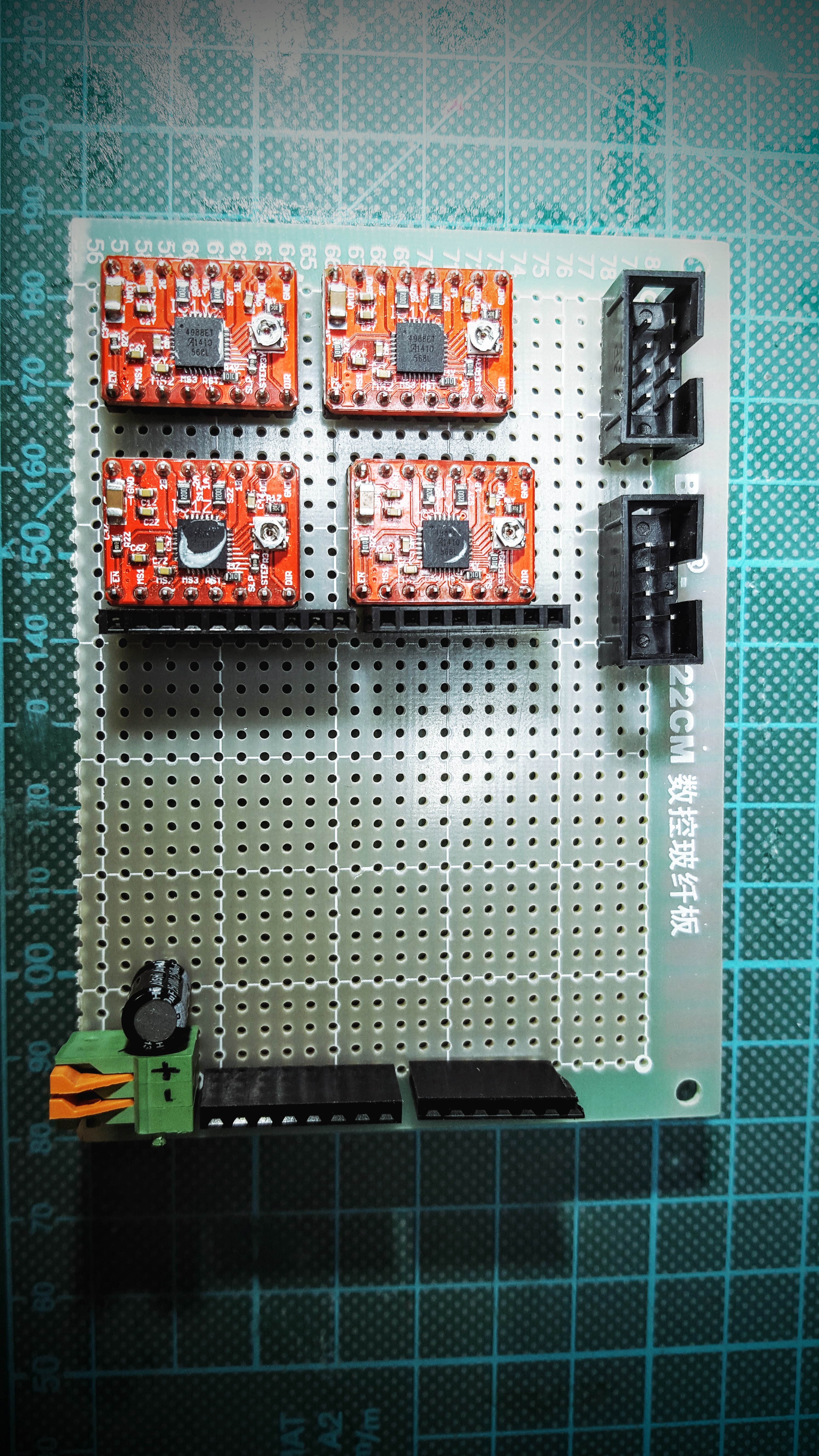
After figuring out that the motor shield didn’t work, I set up to build my own. That way, I could control 4 motors with pololu motor drivers and 1 single arduino.
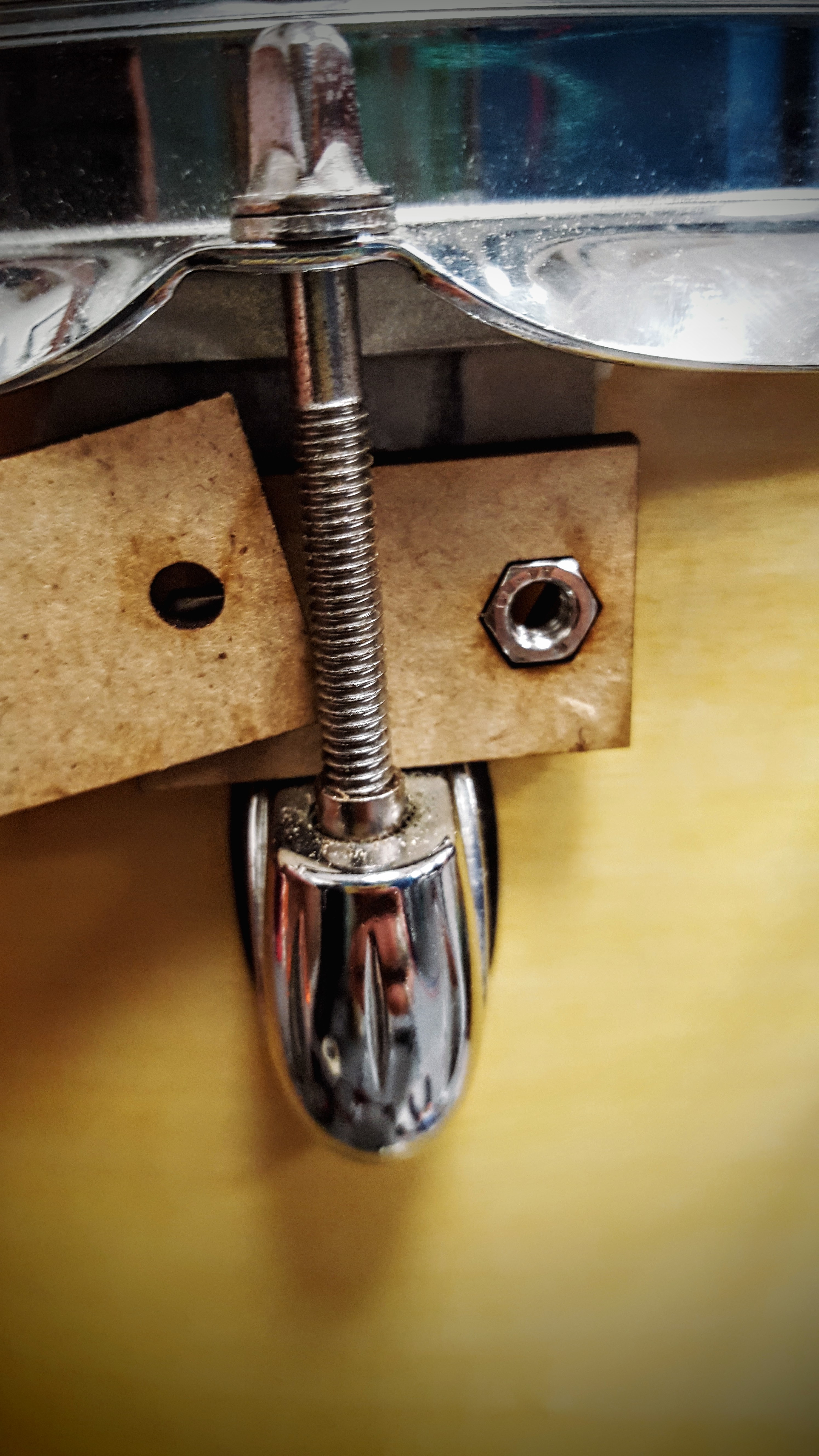
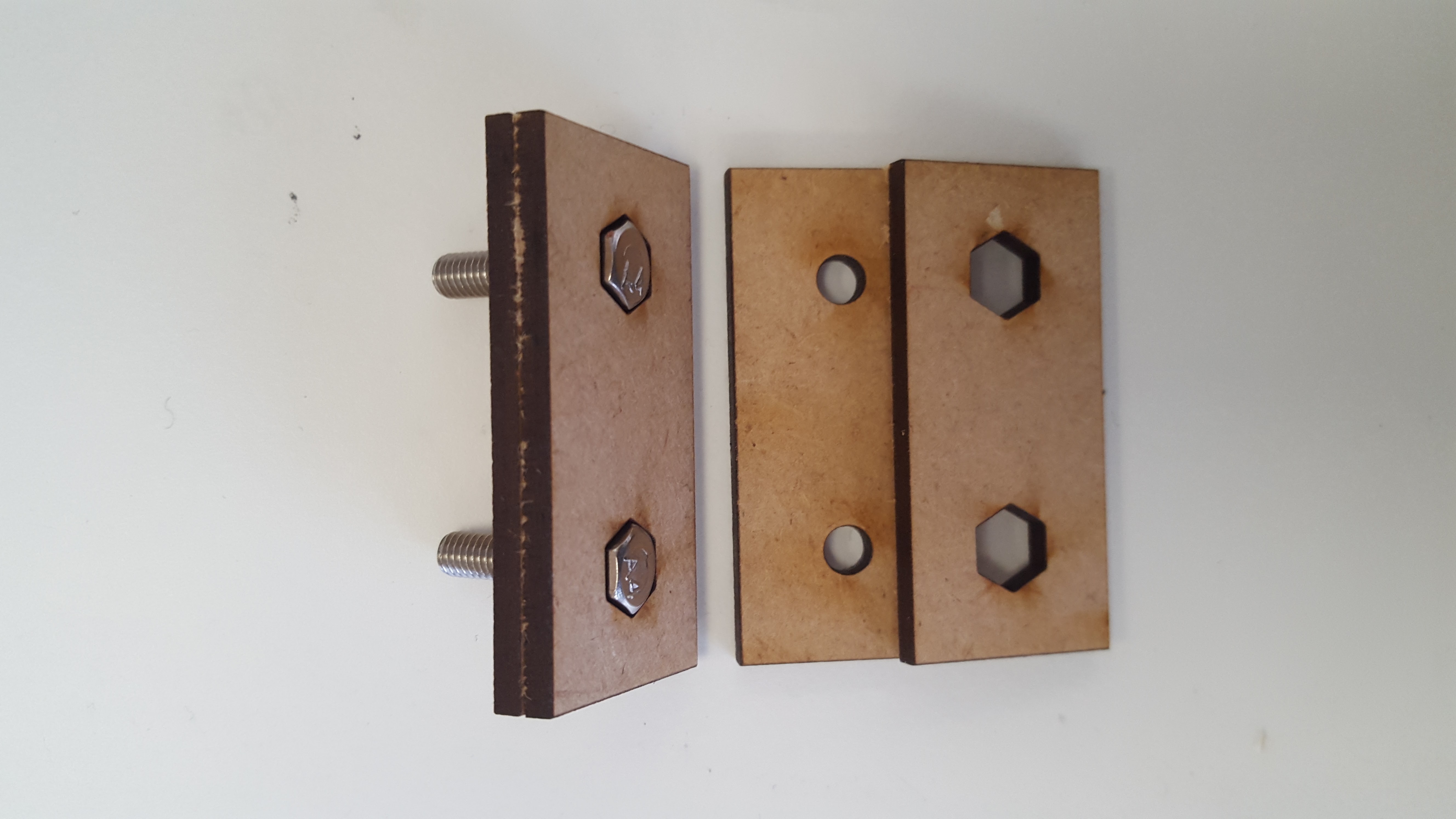
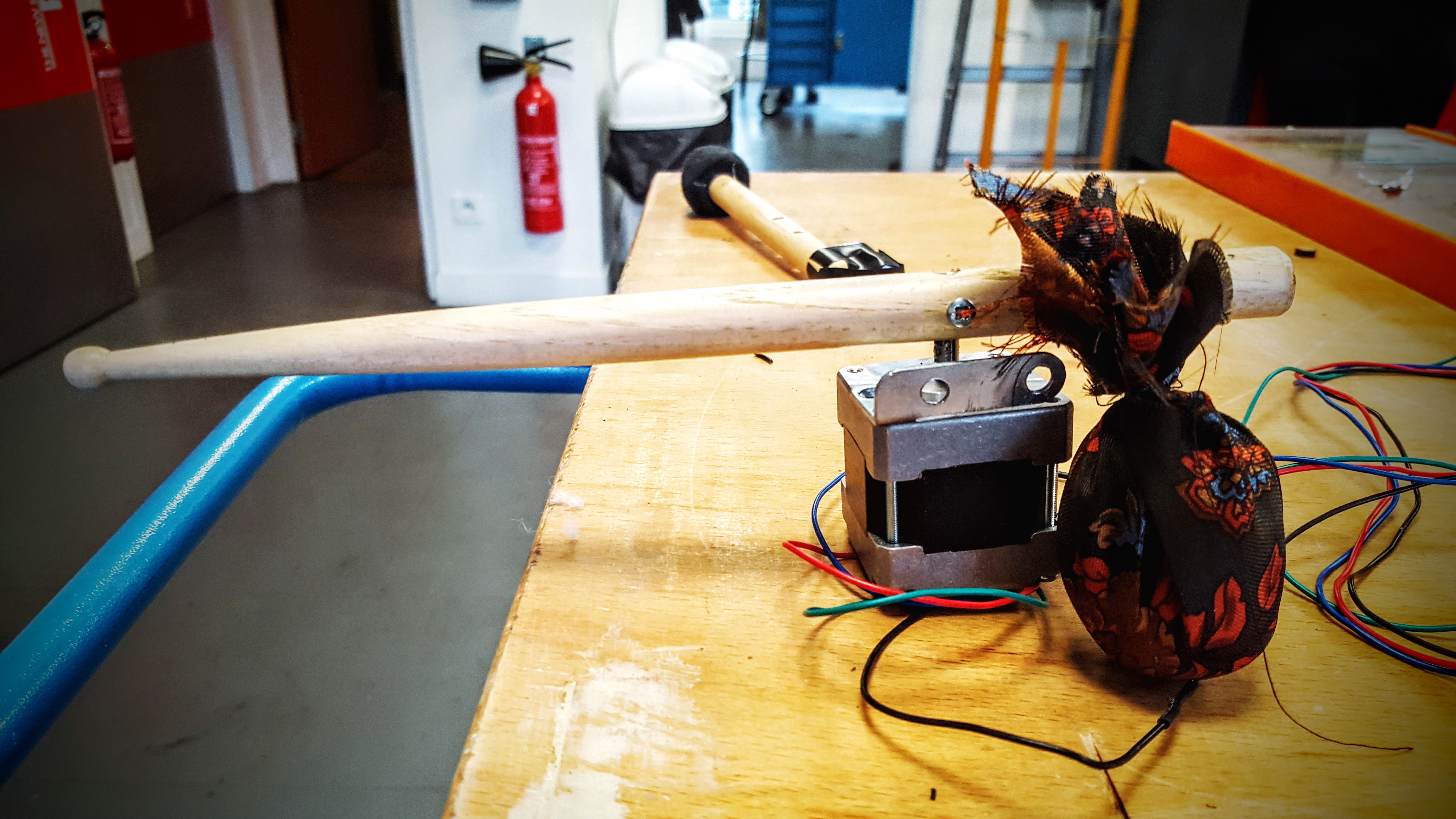
The structure is made with a metal L on top of which I screw the motor. They’re tighten around the screw of the drum with a little structure that allows is to be stable.
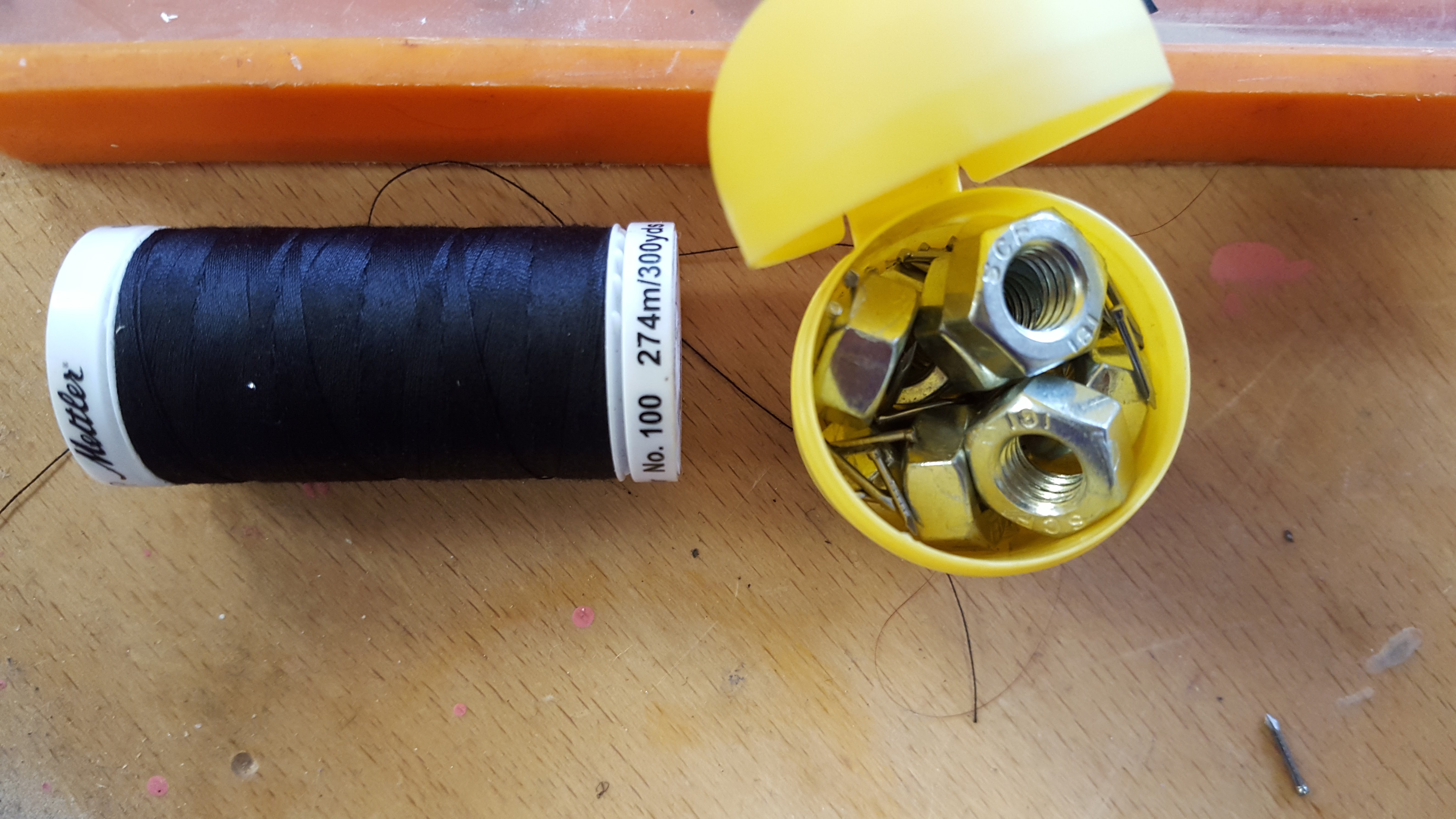
I pierced a hole in the drumsticks to put them on the axis of the motors, and found different ways to counterbalance them (if they’re not counter balanced, they don’t come back once they hit the drum):
It ends up looking like this:
The code is simple enough. I used the Accelstepper library on Arduino, which allows to control not only the speed but also the acceleration of the motors. That way I had different variables to play with.
//instead of calling M1(1,3,2)
AccelStepper M[] = {M0, M1, M2, M3};
int ms1 = 12 , ms2 = 11, ms3 = 10;; // déclaration des broches controlant le micro stepping (la valeur résultante est commune à tous les modules)
//int var = random (0,3);
int temps = 0;
int distance = 50;
int pos = 60; //number of steps (one revolution = 200)
int stopIt = 0;
void setup() {
// put your setup code here, to run once:
//the Move function tell the motor the distance it will have to run
M[1].move(50);
M[2].move(70);
M[3].move(70);
//the run function makes the motor move to the distance set with move()
while (M[1].distanceToGo() > 0){
M[1].run();
}
while (M[2].distanceToGo() > 0){
M[2].run();
}
while (M[3].distanceToGo() > 0){
M[3].run();
}
delay (50);
//Set the motors to hit, then go back to their original position:
M[1].move(-50);
M[2].move(-70);
M[3].move(-70);
while (M[1].distanceToGo() < 0) {
M[1].run();
}
while (M[2].distanceToGo() < 0) {
M[2].run();
}
while (M[3].distanceToGo() < 0){
M[3].run();
}
}
delay(900000); // 15 minutes is the time the lam programer stays on. The delay is set so that
//it doesn’t keep playing for 15 mn.
}
Because the motors end up having different behaviors than expected (probably a problem in the shield I built), the clock turns out to have some sort of life of its own.
I wanted to produce a series of rhythmic samples that would randomly be activated every hour. That turned out to be impossible given the autonomous rebel behavior of my motors.
In a way, I prefer having it this way. It feels as if it has a life of its own and the capacity to make its own decisions, and I created some kind of Frankenstein.
Instructables Link to build your own: http://www.instructables.com/id/AbstractC-a-Drum-Clock/